Mitsubishi Lancer Evolution IX. Manual - part 300
 

  Index      Mitsubishi     Mitsubishi Lancer Evolution IX - service repair manual


Search            


Content   ..  298  299  300  301   ..


Mitsubishi Lancer Evolution IX. Manual - part 300


PROPELLER SHAFT

PROPELLER SHAFT

25-3

PROPELLER SHAFT

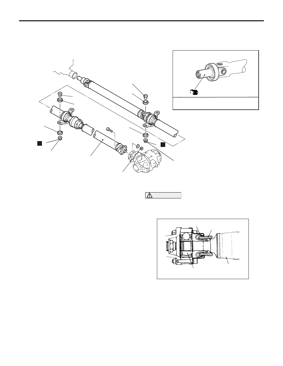
REMOVAL AND INSTALLATION

M1251001000364

AC310408

N

N

32 ± 2 N·m

30 ± 4 N·m

4

2

3

1

1

2

3

Gear Oil:
DIA QUEEN LSD gear oil

30 ± 4 N·m

2

AC

2

Removal steps 

1.

Self locking nut

2.

Insulator

3.

Spacer

<<

A

>> >>

A

<< 4.

Propeller shaft assembly

REMOVAL SERVICE POINT
<<A>> PROPELLER SHAFT ASSEMBLY 
REMOVAL

1. Make mating marks on the differential companion 

flange and the propeller shaft assembly.

CAUTION

Be careful not to bend the joint portion when 
removing the propeller shaft because this will 
damage to the joint boot.

AC101255

Rear propeller
shaft

Joint assembly

Rag

Joint boot

AD

2. Insert a rag so as to avoid boot damage, and 

remove the propeller shaft assembly in a straight 
and level manner.

PROPELLER SHAFT

PROPELLER SHAFT

25-4

INSTALLATION SERVICE POINT
>>A<< PROPELLER SHAFT ASSEMBLY 
INSTALLATION

CAUTION

AC211569

Transfer

Oil seal

AC

Do not damage the oil seal lips on the transfer 

case.

• Remove oil and grease from the threads of 

the mounting bolts and nuts before tighten-
ing, or they will loosen.

AC003833

Mating marks

AC

Be careful not to bend the joint portion when 
removing the propeller shaft,  because this 
will damage the joint boot.

1. If reusing the propeller shaft, align the mating 

marks of differential companion flange and 
propeller shaft assembly to install.

2. When installing a new rear propeller shaft 

assembly, if there is no phase alignment mark on 
the companion flange at the differential side, 
assemble while adjusting the hole phases of 
propeller shaft flange and differential companion 
flange.

INSPECTION

M1251001100219

• Check the sleeve yoke and centre yoke for wear, 

damage or cracks.

• Check the propeller shaft for bends, twisting or 

damage.

• Check the universal joint for smooth operation in 

all directions.

• Check the centre bearing for smooth movement.

PROPELLER SHAFT RUNOUT

ACX00643AB

Limit: 0.5 mm

PROPELLER SHAFT UNIVERSAL JOINT 
PLAY CHECK

AC501206

1. Hold the tube of propeller shaft by one hand, and 

apply force by the other hand to the flange yoke or 
sleeve yoke in rotative direction, axial direction, 
and perpendicular direction for cheking 
looseness.

2. If looseness is recognized, replace the propeller 

shaft with a new one.

PROPELLER SHAFT

PROPELLER SHAFT

25-5

DISASSEMBLY AND REASSEMBLY

M1251001200249

AC211583

14

11

16

12

13

15

14

11

12

15

2

1

N

3

4

5

10

34 ± 5 N·m

9

8

7

N

187 ± 29 N·m

11

N

14

N

13

15

12

N

16

N

6

17

LJ kit

LJ boot kit

AC

187 ± 29 N·m

14

34 ± 5 N·m

Disassembly steps 

1.

Bolt

2.

Front propeller shaft assembly

>>

E

<< 3.

Self locking nut

<<

A

>> >>

E

<< 4.

Companion flange

<<

B

>> >>

E

<< 5.

Centre bearing assembly

<<

C

>>

6.

Bolt

>>

D

<< 7.

Self locking nut

<<

A

>> >>

D

<< 8.

Companion flange

>>

D

<< 9.

Centre bearing assembly

10. Centre propeller shaft
11. Snap ring

>>

C

<< 12. Boot band

<<

D

>> >>

B

<< 13. LJ assembly

14. Rubber packing

<<

E

>> >>

A

<< 15. LJ boot

16. Washer
17. Rear propeller shaft

Disassembly steps (Continued)

PROPELLER SHAFT

PROPELLER SHAFT

25-6

Lubrication and Adhesive Points

AC211584

Rubber
mount

Repair kit grease:
Quantity: 75 ± 5 g 

Adhesive: 3M Stud Locking 4170 or
equivalent

AC


Content   ..  298  299  300  301   ..