Mitsubishi Lancer Evolution IX. Manual - part 237
 

  Index      Mitsubishi     Mitsubishi Lancer Evolution IX - service repair manual


Search            


Content   ..  235  236  237  238   ..


Mitsubishi Lancer Evolution IX. Manual - part 237


SYMPTOM PROCEDURES

SMART WIRING SYSTEM (SWS) USING SWS MONITOR

54C-207

NOTE: 

Prior to the wiring harness inspection, check interme-
diate connector C-129 <high-beam indicator>, and 
repair if necessary.

• Check the output lines for open circuit.

Q: Is the check result normal?

YES : 

Go to Step 7.

NO : 

Repair the wiring harness.

Step 7. Retest the system.
Check that the headlamps and the high-beam indica-
tor lamp illuminate/extinguish normally.

Q: Is the check result normal?

The lamps illuminate normally at both high and low 
beams. : 

The trouble can be an intermittent 

malfunction (Refer to GROUP 00 

− How to 

Cope with Intermittent Malfunction 

P.00-5

).

When the headlamps do not illuminate : 

Replace 

the headlamp socket.

When the high-beam indicator lamp does not 
illuminate : 

Replace the combination meter.

AC310446

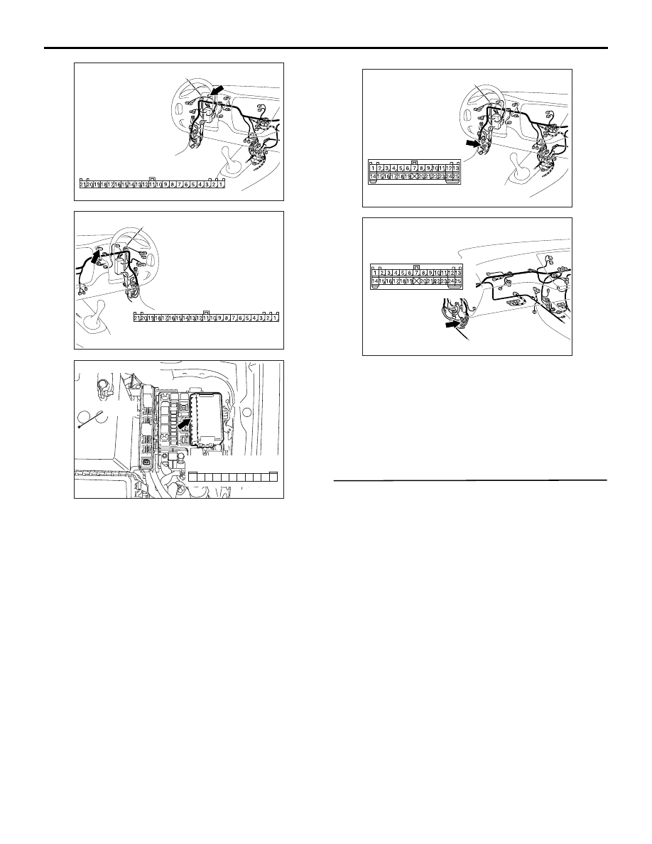
Connector: C-01
<LHD>

AM

Harness side

AC310456

Connector: C-01
<RHD>

AL

Harness side

AC310572AB

Connector: A-10X

Relay box side

10

11

5

9 8 7 6

4 3

1

2

Battery

AC310446

Connector: C-129
<LHD>

AI

AC310454

Connector: C-129
<RHD>

AJ

SYMPTOM PROCEDURES

SMART WIRING SYSTEM (SWS) USING SWS MONITOR

54C-208

FLASHER TIMER

INSPECTION PROCEDURE I-1: The turn-signal lamps do not illuminate.

CAUTION

Whenever the ECU is replaced, ensure that the 
input and output signal circuits are normal.

Wire colour code
B : Black     LG : Light green     G : Green     L : Blue     W : White     Y : Yellow     SB : Sky blue
BR : Brown     O : Orange     GR : Gray     R : Red     P : Pink     V : Violet

BATTERY

ETACS-ECU

RELAY
BOX

TURN-SIGNAL
LAMP RELAY: LH

TURN-SIGNAL
LAMP RELAY: RH

· HEADLAMP
  ASSEMBLY (LH)
· SIDE TURN SIGNAL
  LAMP (LH)

REAR
COMBINATION
LAMP (LH)

COMBINATION
METER

· COMBINATION
  METER
· HEADLAMP
  ASSEMBLY (RH)

· SIDE TURN SIGNAL
  LAMP (RH)
· REAR COMBINATION
  LAMP (RH)

J/B SIDE

Turn-Signal Lamp Power Supply Circuit <LHD>

SYMPTOM PROCEDURES

SMART WIRING SYSTEM (SWS) USING SWS MONITOR

54C-209

COMMENTS ON TROUBLE SYMPTOM

If all the turn-signal lamps do not illuminate, the igni-
tion switch (IG1), the turn-signal lamp switch input 
circuit or the ETACS-ECU may be defective.

POSSIBLE CAUSES

• Malfunction of the column switch

• Malfunction of the ETACS-ECU

• Damaged harness wires and connectors

DIAGNOSIS PROCEDURE

Step 1. Check that the hazard warning lamps 
operate.
Check that the hazard warning lamps illuminate nor-
mally.

Q: Is the check result normal?

YES : 

Go to Step 6.

NO : 

Go to Step 2.

Wire colour code
B : Black     LG : Light green     G : Green     L : Blue     W : White     Y : Yellow     SB : Sky blue
BR : Brown     O : Orange     GR : Gray     R : Red     P : Pink     V : Violet

BATTERY

ETACS-ECU

RELAY
BOX

TURN-SIGNAL
LAMP RELAY: LH

TURN-SIGNAL
LAMP RELAY: RH

· HEADLAMP
  ASSEMBLY (LH)
· SIDE TURN SIGNAL
  LAMP (LH)
· REAR COMBINATION
  LAMP (LH)

REAR
COMBINATION
LAMP (RH)

COMBINATION
METER

· HEADLAMP
  ASSEMBLY (RH)
· SIDE TURN SIGNAL
  LAMP (RH)

J/B SIDE

Turn-Signal Lamp Power Supply Circuit <RHD>

SYMPTOM PROCEDURES

SMART WIRING SYSTEM (SWS) USING SWS MONITOR

54C-210

Step 2. Connector check: C-226 ETACS-ECU 
connector

Q: Is the check result normal?

YES : 

Go to Step 3.

NO : 

Repair the defective connector.

Step 3. Voltage measurement at the C-226 
ETACS-ECU connector

(1) Remove the ETACS-ECU, and measure at the 

junction block side.

(2) Voltage between C-226 ETACS-ECU connector 

terminal No.11 and body earth

OK: System voltage

Q: Is the check result normal?

YES : 

Go to Step 5.

NO : 

Go to Step 4.

AC310450

Connector: C-226

AB

Junction block side

Junction block (rear view)

<LHD>

AC310461

Junction block (rear view)

Connector: C-226

AB

<RHD>

Junction block side

AC310450

Connector: C-226

AB

Junction block side

Junction block (rear view)

<LHD>

AC310461

Junction block (rear view)

Connector: C-226

AB

<RHD>

Junction block side

AC301541HF

Connector C-226
(Junction block side)

2019

7

13

17

18

1615 14

10

11

12

9 8

2

6 5

3

4

1


Content   ..  235  236  237  238   ..