Mitsubishi Lancer Evolution IX. Manual - part 233
 

  Index      Mitsubishi     Mitsubishi Lancer Evolution IX - service repair manual


Search            


Content   ..  231  232  233  234   ..


Mitsubishi Lancer Evolution IX. Manual - part 233


SYMPTOM PROCEDURES

SMART WIRING SYSTEM (SWS) USING SWS MONITOR

54C-191

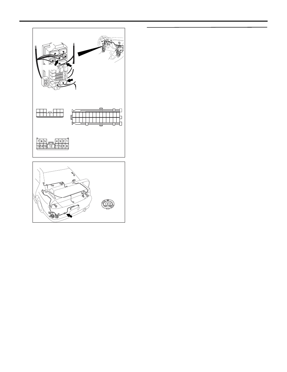
Prior to the wiring harness inspection, check interme-
diate connector C-129 <tail lamp LH, licence plate 
lamp or tail lamp indicator>, C-113 <tail lamp RH> or 
F-12 <licence plate lamp>, joint connector C-05 <tail 
lamp RH>, junction block connector C-210 <tail lamp 
LH, licence plate lamp or tail lamp indicator>, C-214 
<tail lamp indicator> or C-217 <tail lamp LH or 
licence plate lamp> and repair if necessary.

• Check the output lines for open circuit.

Q: Is the check result normal?

YES : 

Go to Step 7.

NO : 

Repair the wiring harness.

Step 7. Retest the system.
Check that the tail lamps, the position lamps and the 
licence plate lamps illuminate normally.

Q: Is the check result normal?

The all lamps illuminate normally : 

The trouble can 

be an intermittent malfunction (Refer to 
GROUP 00 

− How to Cope with Intermittent 

Malfunction 

P.00-5

).

When the tail lamps do not illuminate : 

Replace 

the rear combination lamp socket assembly.

When the position lamps do not illuminate : 

Replace the position lamp socket.

When the licence plate lamps do not illuminate : 

Replace the licence plate lamp socket.

When the tail lamp indicator do not illuminate : 

Replace the combination meter assembly.

AC310449

C-214
Harness side

21

7

16 15

17

18

20 19

1

2

3

4

5

6

23 22

24

25

28

26

27

9

8

10

11

14

12

13

Connectors: C-210, C-214, C-217

AE

C-214

Junction block (front view)

<LHD>

C-210

C-210
Harness side

10

1

6

14

5

12

13

4

11

7

2

3

8

9

C-217

C-217
Harness side

AC310467AG

Connector: F-12 <LHD>

F-12 (GR)

SYMPTOM PROCEDURES

SMART WIRING SYSTEM (SWS) USING SWS MONITOR

54C-192

INSPECTION PROCEDURE H-7: Any of tail lamps, position lamps or licence plate lamps does not 

illuminate. <RH drive vehicles>

CAUTION

Whenever the ECU is replaced, ensure that the 

input and output signal circuits are normal.

TAIL LAMP
RELAY

REAR
COMBINATION
LAMP (RH)

LICENCE
PLATE
LAMP

(LH)

(RH)

COMBINATION
METER

REAR
COMBINATION
LAMP (LH)

FRONT-ECU

(LH)

(RH)

RELAY
BOX

HEADLAMP
ASSEMBLY

Wire colour code
B : Black     LG : Light green     G : Green     L : Blue     W : White     Y : Yellow     SB : Sky blue
BR : Brown     O : Orange     GR : Gray     R : Red     P : Pink     V : Violet

Taillamps, Position Lamps and License Plate Lamps Circuit <RHD>

SYMPTOM PROCEDURES

SMART WIRING SYSTEM (SWS) USING SWS MONITOR

54C-193

COMMENTS ON TROUBLE SYMPTOM

If the tail lamps, the position lamps or the licence 
plate lamps do not illuminate, the wiring harness con-
nector(s), the bulb or the fuse may be defective or 
burned out.

POSSIBLE CAUSES

• Burned-out bulb

• Damaged harness wires and connectors

DIAGNOSTIC PROCEDURE

Step 1. Connector check: F-14 <tail lamp LH> or 

F-08 <tail lamp RH> rear combination lamp 

connector, A-31 <position lamp LH> or A-39 

<position lamp RH> headlamp assembly 

connector, F-11 <licence plate lamp LH> or F-10 

<licence plate lamp RH> licence plate lamp 

connector, C-02 <tail lamp indicator> 

combination meter connector

Q: Is the check result normal?

YES : 

Go to Step 2.

NO : 

Repair the defective connector.

Step 2. Check the bulbs of the tail lamps, the 
position lamp, the licence plate lamp or tail lamp 
indicator.
Check the bulb of the lamp which does not illumi-
nate.

Q: Is the check result normal?

YES : 

Go to Step 3.

NO : 

Replace the bulb of the lamp which does not 
illuminate.

AC310470

Connectors: F-08, F-10, F-11, F-14

<RHD>

AD

F-08(B)

F-10(GR)

F-11(GR)

F-14(B)

Harness side

F-08

Harness side

F-11

Harness side

F-10

Harness side

F-14

AC310475

Connectors: A-31

AB

A-31(B)

Harness side

A-31

<RHD>

AC310433

Connectors: A-39

AD

A-39(B)

Harness side

A-39

<RHD>

AC310456

Connector: C-02
<RHD>

AK

Harness side

31

35

36

37

38

39

40

41

45

46

47

48

49

50

51

34

44

33

43

32

42

C-02 (L)

SYMPTOM PROCEDURES

SMART WIRING SYSTEM (SWS) USING SWS MONITOR

54C-194

Step 3. Resistance measurement at the F-14 <tail 

lamp LH> or F-08 <tail lamp RH> rear 

combination lamp connector, the A-31 <position 

lamp LH> or A-39 <position lamp RH> headlamp 

assembly connector, the F-11 <licence plate lamp 

LH> or F-10 <licence plate lamp RH> licence 

plate lamp connector or C-02 <tail lamp 

indicator> combination meter connector

(1) Disconnect the connector, and measure at the 

wiring harness side.

(2) Check the resistance between the lamp 

connector and body earth.

Resistance between A-31 <position lamp LH> 

headlamp assembly connector terminal No.6 
and body earth

• Resistance between A-39 <position lamp 

RH> headlamp assembly connector terminal 
No.6 and body earth

Resistance between F-14 <tail lamp LH> rear 

combination lamp connector terminal No.5 
and body earth

• Resistance between F-08 <tail lamp RH> rear 

combination lamp connector terminal No.5 
and body earth

AC310470

Connectors: F-08, F-10, F-11, F-14

<RHD>

AD

F-08(B)

F-10(GR)

F-11(GR)

F-14(B)

Harness side

F-08

Harness side

F-11

Harness side

F-10

Harness side

F-14

AC310475

Connectors: A-31

AB

A-31(B)

Harness side

A-31

<RHD>

AC310433

Connectors: A-39

AD

A-39(B)

Harness side

A-39

<RHD>

AC310456

Connector: C-02
<RHD>

AK

Harness side

31

35

36

37

38

39

40

41

45

46

47

48

49

50

51

34

44

33

43

32

42

C-02 (L)

AC301541HP

Connector A-31, A-39
(Harness side)

AC301541HN

Connector F-08, F-14
(Harness side)


Content   ..  231  232  233  234   ..