Mitsubishi Lancer Evolution IX. Manual - part 206
 

  Index      Mitsubishi     Mitsubishi Lancer Evolution IX - service repair manual


Search            


Content   ..  204  205  206  207   ..


Mitsubishi Lancer Evolution IX. Manual - part 206


SYMPTOM PROCEDURES

SMART WIRING SYSTEM (SWS) USING SWS MONITOR

54C-83

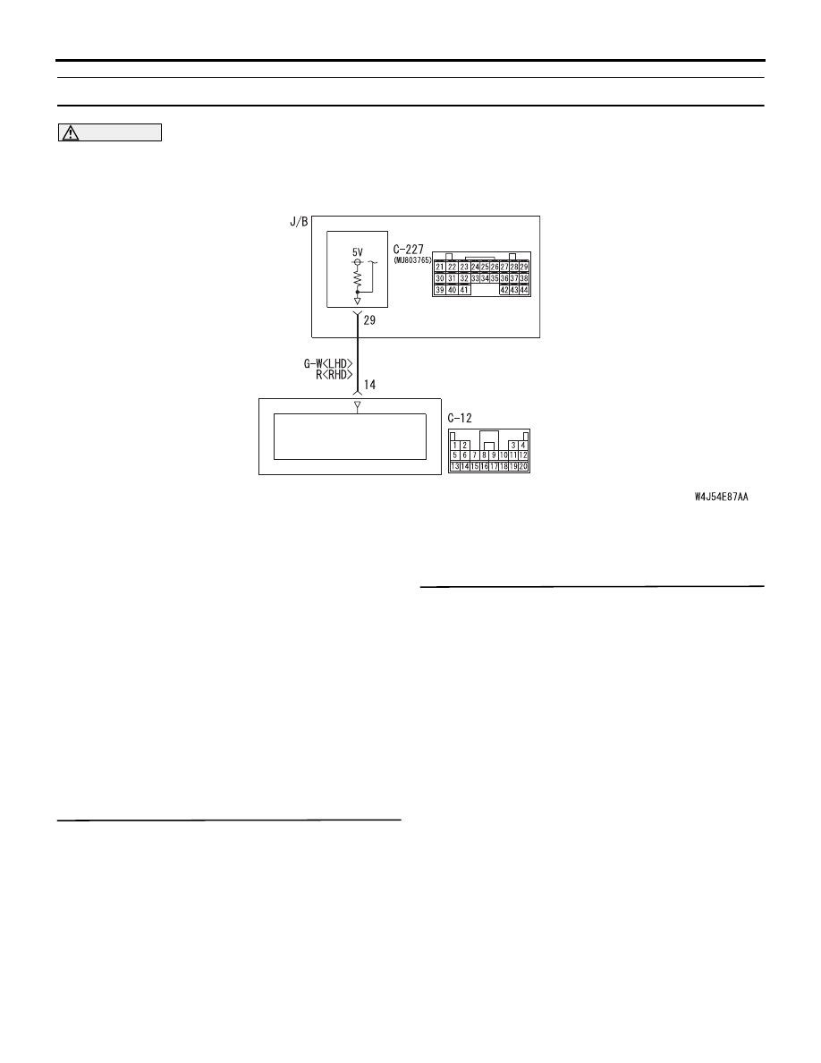
INSPECTION PROCEDURE C-5: The impact detection door unlock function does not function.

CAUTION

Whenever the ECU is replaced, ensure that the 
input and output signal circuits are normal.

COMMENTS ON TROUBLE SYMPTOM

If the impact detection door unlock function does not 
work normally, the input signal circuit from the impact 
detection sensor, the SRS-ECU or the ETACS-ECU 
may be defective.

POSSIBLE CAUSES

• Malfunction of the SRS-ECU

• Malfunction of the ETACS-ECU

• Damaged harness wires and connectors

DIAGNOSIS PROCEDURE

Step 1. M.U.T.-II/III other system diagnosis code.
Check that the SRS-ECU sets a diagnosis code.

Q: Is the diagnosis code set?

YES : 

Refer to GROUP 52B 

− Troubleshooting 

P.52B-9

.

NO : 

Go to Step 2.

Step 2. ECU check by using the SWS monitor.
Check that the power supply and earth lines to the 
ETACS-ECU and the SWS communication lines are 
normal.

• Ignition switch: OFF

ECUS TO BE CHECKED

• ETACS ECU

OK: "OK" is displayed on the "ETACS ECU" 
menu.

Q: Is the check result normal?

YES : 

Go to Step 3.

NO : 

Refer to Inspection Procedure A-3 
"Communication with the ETACS-ECU is 
not possible 

P.54C-36

."

Wire colour code
B : Black     LG : Light green
G : Green     L : Blue
W : White     Y : Yellow
SB : Sky blue     BR : Brown
O : Orange     GR : Gray
R : Red     P : Pink     V : Violet

SRS-ECU

ETACS-ECU

CRASH DETECTION
DOOR UNLOCK
SIGNAL PROCESS CIRCUIT

SYMPTOM PROCEDURES

SMART WIRING SYSTEM (SWS) USING SWS MONITOR

54C-84

Step 3. Connector check: C-12 SRS-ECU 
connector and C-227 ETACS-ECU connector

Q: Are the check results normal?

YES : 

Go to Step 4.

NO : 

Repair the defective connector.

Step 4. Check the wiring harness between C-227 
ETACS-ECU connector terminal No.29 and C-12 
SRS-ECU connector terminal No.14.

• Check the communication lines for open circuit.

Q: Is the check result normal?

YES : 

Go to Step 5.

NO : 

Repair the wiring harness.

AC310446

Connector: C-12 <LHD>

AZ

Harness side

C-12 (Y)

AC310454

Connector: C-12 <RHD>

BE

Harness side

C-12 (Y)

AC310450

Connector: C-227 <LHD>

AI

Junction block side (rear view)

Harness side

21

22

23

24

25

26

27

28

29

30

31

32

33

34

35

36

37

38

39

40

41

42

43

44

AC310461

Harness side

Junction block (rear view)

Connector: C-227

AF

<RHD>

21

22

23

24

25

26

27

28

29

30

31

32

33

34

35

36

37

38

39

40

41

42

43

44

AC310446

Connector: C-12 <LHD>

AZ

Harness side

C-12 (Y)

AC310454

Connector: C-12 <RHD>

BE

Harness side

C-12 (Y)

AC310450

Connector: C-227 <LHD>

AI

Junction block side (rear view)

Harness side

21

22

23

24

25

26

27

28

29

30

31

32

33

34

35

36

37

38

39

40

41

42

43

44

AC310461

Harness side

Junction block (rear view)

Connector: C-227

AF

<RHD>

21

22

23

24

25

26

27

28

29

30

31

32

33

34

35

36

37

38

39

40

41

42

43

44

SYMPTOM PROCEDURES

SMART WIRING SYSTEM (SWS) USING SWS MONITOR

54C-85

Step 5. Retest the system.
Replace the SRS-ECU, and check that the impact 
detection door unlock function works normally.
(1) Replace the SRS-ECU.
(2) Check that the impact detection door unlock 

function works normally.

Q: Is the check result normal?

YES : 

The trouble can be an intermittent 

malfunction (Refer to GROUP 00 

− How to 

Cope with Intermittent Malfunction 

P.00-5

).

NO : 

Replace the ETACS-ECU.

SYMPTOM PROCEDURES

SMART WIRING SYSTEM (SWS) USING SWS MONITOR

54C-86

POWER WINDOW

INSPECTION PROCEDURE D-1: Power windows do not work at all.

CAUTION

Whenever the ECU is replaced, ensure that the 
input and output signal circuits are normal.

POWER WINDOW 
RELAY

ETACS-ECU

FRONT 
POWER 
WINDOW 
SUB 
SWITCH 
(RH)

REAR 
POWER 
WINDOW 
SUB 
SWITCH 
(LH)

REAR 
POWER 
WINDOW 
SUB 
SWITCH 
(RH)

Wire colour code
B : Black 
LG : Light green
G : Green
L: Blue 
W : White
Y: Yellow
SB : Sky blue
BR : Brown 
O : Orange
GR : Gray  
R : Red 
P : Pink  
V : Violet       

J/B SIDE

CPU

Power Window Relay Circuit <LHD>

FUSIBLE 
LINK

5

POWER WINDOW 
MAIN SWITCH


Content   ..  204  205  206  207   ..