Mitsubishi Lancer Evolution IX. Manual - part 187
 

  Index      Mitsubishi     Mitsubishi Lancer Evolution IX - service repair manual


Search            


Content   ..  185  186  187  188   ..


Mitsubishi Lancer Evolution IX. Manual - part 187


TROUBLESHOOTING

SMART WIRING SYSTEM (SWS) USING SWS MONITOR

54C-7

AC310447

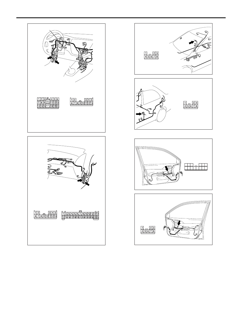
Connectors: C-17, C-127

AH

<LHD>

C-17

C-17

C-127

C-127

AC310453

Connectors: C-110, C-113

AC

<LHD>

C-110

C-110

C-113

C-113

AC310463

AE

Connector: D-04

<LHD>

AC310465

AE

Connector: D-15
<LHD>

AC310484AF

Connector: E-05 <LHD>

Front door (LH)

11

10

1

6

14

5

12 13

4

7

2 3

8 9

AC310488

Connector: E-14

AF

<LHD>

Front door (RH)

TROUBLESHOOTING

SMART WIRING SYSTEM (SWS) USING SWS MONITOR

54C-8

<RH DRIVE VEHICLES>

AC310486

Connector: E-08

AF

Rear door (LH)

AC310491

Connector: E-17

AE

Rear door (RH)

Connector name

Connector number

Terminal No.

Intermediate connector

Instrument panel wiring 
harness and floor wiring 
harness (LH) combination

C-17 [Front door wiring harness 
(LH) side]

8

Instrument panel wiring 
harness and front door wiring 
harness (RH) combination

C-110 [Front door wiring 
harness (RH) side]

7

Instrument panel wiring 
harness and front door wiring 
harness (LH) combination

C-113(Instrument panel wiring 
harness side)

2

Instrument panel wiring 
harness and floor wiring 
harness (LH) combination

C-127 (Instrument panel wiring 
harness side)

13

Floor wiring harness (RH) and 
rear door wiring harness (RH) 
combination

D-04 [Floor wiring harness (RH) 
side]

7

Floor wiring harness (LH) and 
rear door wiring harness (LH) 
combination

D-15 [Floor wiring harness (LH) 
side]

7

Power window main switch

E-05

11

Front power window sub switch

E-14

6

Rear power window sub switch (RH)

E-17

6

Rear power window sub switch (LH)

E-08

6

TROUBLESHOOTING

SMART WIRING SYSTEM (SWS) USING SWS MONITOR

54C-9

AC310457

Connectors: C-110, C-113

AC

<RHD>

C-110

C-113

C-110

C-113

AC310455

Connectors: C-17, C-127

AF

<RHD>

C-17

C-127

C-127

C-17

AC310471

AE

Connector: D-04
<RHD>

AC310473

AF

Connector: D-15 <RHD>

AC310493

AI

Connector: E-05
<RHD>

Front door (RH)

11

10

1

6

14

5

12 13

4

7

2 3

8 9

AC310498

Connector: E-14
<RHD>

AE

Front door (LH)

TROUBLESHOOTING

SMART WIRING SYSTEM (SWS) USING SWS MONITOR

54C-10

ECU CHECK

M1549014900457

Use the M.U.T.-II/III and the SWS monitor to check 

ECUs (Refer to M.U.T.-II Reference Manual or 
M.U.T.-III User’s Manual).

1. The following ECUs can be checked by using the 

M.U.T.-II/III and the SWS monitor.
NOTE: If a malfunction is found by the "ECU 
Check," proceed "Symptom Procedure" (Refer to 

P.54C-20

).

SWS MONITOR-COMPATIBLE ECUS AND THEIR CONDITIONS

NOTE: 

.

*1

: If "NG" is displayed beside the ETACS-ECU while the ignition switch is off, "NG" is also displayed 

beside the column-ECU.

*2

: If "NG" is displayed beside the ETACS-ECU, "NG" is also displayed beside the front-ECU and the 

power window main switch (power window module).

AC310486

Connector: E-08

AF

Rear door (LH)

AC310491

Connector: E-17

AE

Rear door (RH)

Item 
No.

ECUs to be checked

Display on 
M.U.T.-II/III

Normal 
condition

ECU condition

80

Column switch 
(column-ECU)

COLUMN ECU

OK

*1

All of the column switch, power 
supply, earth and interconnecting 
communication line are normal

83

ETACS-ECU

ETACS ECU

OK

All of the ETACS-ECU switch, 
power supply, earth and 
interconnecting communication line 
are normal

84

Front-ECU

FRONT ECU

OK

*2

All of the front-ECU, power supply, 
earth and interconnecting 
communication line are normal

85

Power window main 
switch (power window 
module)

P/W MODULE

OK

*2

 (when 

the ignition 
switch is ON)

All of the power window main 
switch, power supply, earth and 
interconnecting communication line 
are normal

Other SWS-related ECUs Other ECUs

NG

ECUs are not used


Content   ..  185  186  187  188   ..