Mitsubishi Lancer Evolution IX. Manual - part 181
 

  Index      Mitsubishi     Mitsubishi Lancer Evolution IX - service repair manual


Search            


Content   ..  179  180  181  182   ..


Mitsubishi Lancer Evolution IX. Manual - part 181


INPUT SIGNAL PROCEDURES

SMART WIRING SYSTEM (SWS) NOT USING SWS MONITOR

54B-287

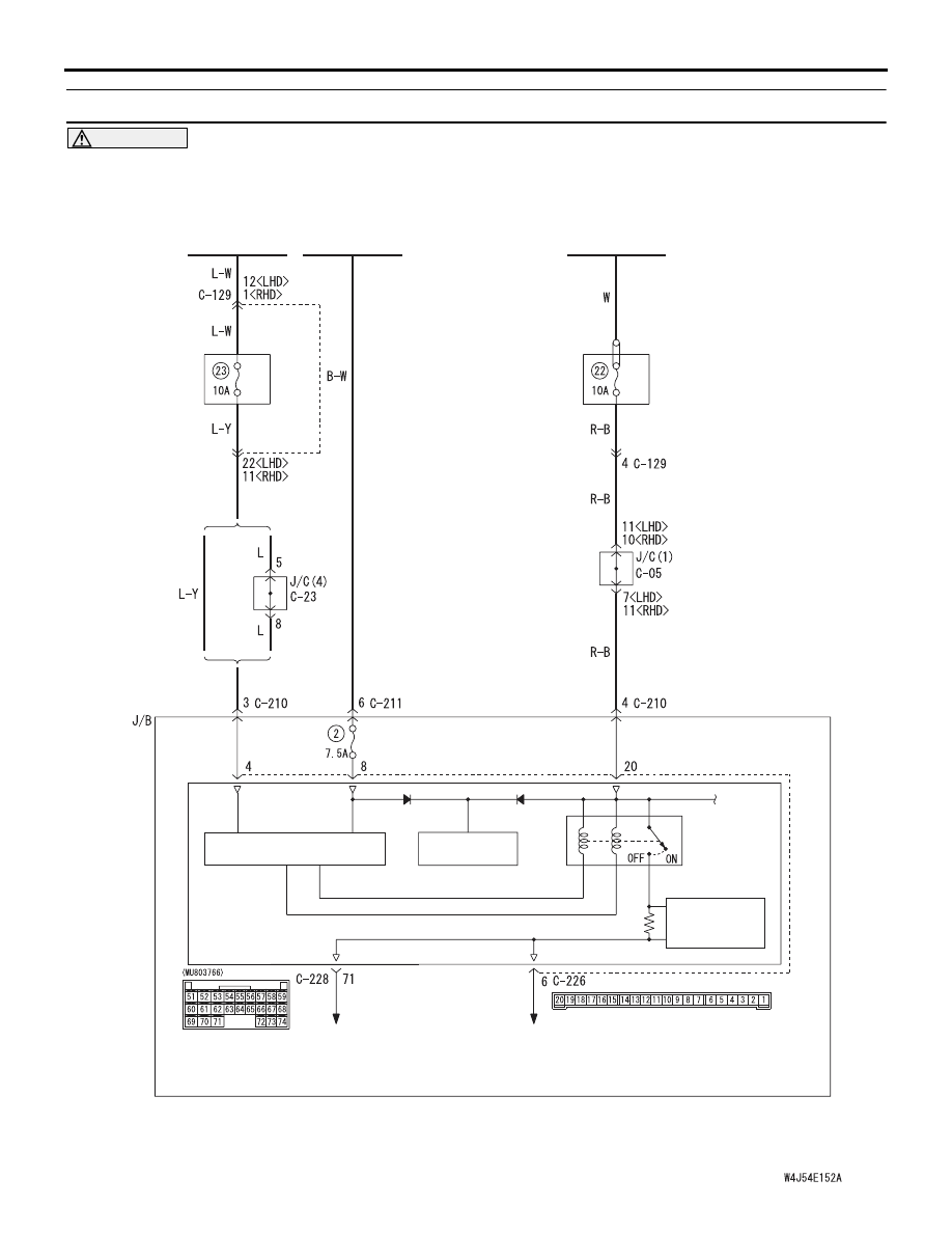
INSPECTION PROCEDURE L-15: Interior lamp loaded signal is not detected.

CAUTION

Whenever the ECU is replaced, ensure that the 

input signal circuit is normal.

IGNITION
SWITCH (IG1)

IGNITION
SWITCH (ACC)

COMBINATION
METER

Wire colour code
B : Black     LG : Light green     G : Green     L : Blue     W : White     Y : Yellow     SB : Sky blue
BR : Brown     O : Orange     GR : Gray     R : Red     P : Pink     V : Violet

KEEP RELAY

ETACS-ECU

INTERIOR LAMP CUT
BACK-UP CIRCUIT

POWER
SOURCE

LOAD
DETERMINATION
CIRCUIT

BATTERY

J/B SIDE

<LHD>

<RHD>

· LUGGAGE COMPARTMENT LAMP
· FRONT ROOM LAMP
· REAR ROOM LAMP

RELAY
BOX

Interior Lamp Automatic Shutdown Function Circuit

INPUT SIGNAL PROCEDURES

SMART WIRING SYSTEM (SWS) NOT USING SWS MONITOR

54B-288

COMMENTS ON TROUBLE SYMPTOM

The interior lamp automatic shutdown function oper-
ates in accordance with the interior lamp loaded sig-
nal. If this signal is abnormal, the functions below will 
not work normally.

• Ignition key cylinder illumination lamp

• Room lamps

POSSIBLE CAUSES

• Malfunction of the ETACS-ECU

• Damaged wiring harness or connector(s)

DIAGNOSTIC PROCEDURE

Step 1. Check the power supply circuit.
When the ignition switch is turned to the LOCK 
(OFF) position, check if the hazard warning lamps 
illuminate.

Q: Is the check result normal?

YES : 

Go to Step 2.

NO : 

Refer to inspection procedure A-2 "Check 
the battery power supply circuit to the 
ETACS-ECU 

P.54B-42

."

Step 2. Connector check: C-226 ETACS-ECU 
connector

Q: Is the check result normal?

YES : 

Go to Step 3.

NO : 

Repair the defective connector.

Step 3. Voltage measurement at the C-226 
ETACS-ECU connector

(1) Remove the ETACS-ECU, and measure at the 

junction block side.

(2) Turn the ignition switch to the ON position.

(3) Voltage between C-226 ETACS-ECU connector 

terminal No.8 and body earth

OK: System voltage

Q: Is the check result normal?

YES : 

Go to Step 5.

NO : 

Go to Step 4.

AC310450

Connector: C-226

AB

Junction block side

Junction block (rear view)

<LHD>

AC310461

Junction block (rear view)

Connector: C-226

AB

<RHD>

Junction block side

AC310450

Connector: C-226

AB

Junction block side

Junction block (rear view)

<LHD>

AC310461

Junction block (rear view)

Connector: C-226

AB

<RHD>

Junction block side

AC301541GU

Connector C-226
(Junction block side)

2019

7

13

17

18

1615 14

10

11

12

9 8

2

6 5

3

4

1

INPUT SIGNAL PROCEDURES

SMART WIRING SYSTEM (SWS) NOT USING SWS MONITOR

54B-289

Step 4. Check the wiring harness between C-226 
ETACS-ECU connector terminal No.8 and the 
ignition switch (IG1).

NOTE: 

Prior to the wiring harness inspection, check junction 
block connector C-211, and repair if necessary.

• Check the power supply line to the ignition switch 

(IG1) for open circuit.

Q: Is the check result normal?

YES : 

The trouble can be an intermittent 

malfunction (Refer to GROUP 00 

− How to 

Cope with Intermittent Malfunction 

P.00-5

).

NO : 

Repair the wiring harness.

Step 5. Voltage measurement at the C-226 
ETACS-ECU connector

(1) Remove the ETACS-ECU, and measure at the 

junction block side.

(2) Turn the ignition switch to the ACC position.

(3) Voltage between C-226 ETACS-ECU connector 

terminal No.4 and body earth

OK: System voltage

Q: Is the check result normal?

YES : 

Go to Step 7.

NO : 

Go to Step 6.

AC310450

Connector: C-226

AB

Junction block side

Junction block (rear view)

<LHD>

AC310461

Junction block (rear view)

Connector: C-226

AB

<RHD>

Junction block side

AC310448

Harness side

Junction block (front view)

Connector: C-211

AB

<LHD>

4

6 5

3

2

1

AC310458

Harness side

Junction block (front view)

Connector: C-211

AB

<RHD>

AC310450

Connector: C-226

AB

Junction block side

Junction block (rear view)

<LHD>

AC310461

Junction block (rear view)

Connector: C-226

AB

<RHD>

Junction block side

AC301541HB

Connector C-226
(Junction block side)

2019

7

13

17

18

1615 14

10

11

12

9 8

2

6 5

3

4

1

INPUT SIGNAL PROCEDURES

SMART WIRING SYSTEM (SWS) NOT USING SWS MONITOR

54B-290

Step 6. Check the wiring harness between C-226 
ETACS-ECU connector terminal No.4 and the 
ignition switch (ACC).

NOTE: 

AC310450

Connector: C-226

AB

Junction block side

Junction block (rear view)

<LHD>

AC310461

Junction block (rear view)

Connector: C-226

AB

<RHD>

Junction block side

AC310456

Connector: C-23

AJ

<RHD>

C-23 (B)

Harness side

AC310448

Junction block (front view)

Connector: C-210

AK

<LHD>

Harness side

10

1

6

14

5

12

13

4

11

7

2

3

8

9

AC310458

Junction block (front view)

Connector: C-210

AH

<RHD>

Harness side

10

1

6

14

5

12

13

4

11

7

2

3

8

9

AC310446

Connector: C-129
<LHD>

AI


Content   ..  179  180  181  182   ..