Mitsubishi Lancer Evolution IX. Manual - part 150
SYMPTOM PROCEDURES
SMART WIRING SYSTEM (SWS) NOT USING SWS MONITOR
54B-163
Step 2. Pulse check
Check the input signal from the headlamp switch.
OK: The M.U.T.-II/III sounds or the voltmeter
needle fluctuates.
Q: Is the check result normal?
All the signals are received normally. :
Go to Step
3.
The ignition switch (IG1) signal is not received. :
Refer to inspection procedure L-2 "The
ignition switch (IG1) signal is not received
."
The headlamp switch signal is not received. :
Refer to inspection procedure L-4 "The
column switch (lighting and turn-signal lamp
switch) signal is not received
Step 3. Connector check: A-10X front-ECU
connector
Q: Is the check result normal?
YES :
Go to Step 4.
NO :
Repair the defective connector.
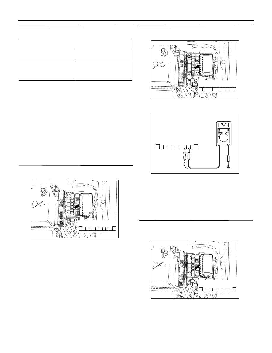
Step 4. Voltage measurement at A-10X front-ECU
connector
(1) Remove the front-ECU, and measure at the relay
box side.
(2) Voltage between A-10X front-ECU connector
terminal Nos.3, 4 and body earth
OK: System voltage
Q: Is the check result normal?
YES :
Go to Step 6.
NO :
Go to Step 5.
Step 5. Check the wiring harness between A-10X
front-ECU connector terminal Nos.3, 4 and the
battery.
• Check the power supply line for open circuit.
Q: Is the check result normal?
YES :
The trouble can be an intermittent
malfunction (Refer to GROUP 00
− How to
Cope with Intermittent Malfunction
NO :
Repair the wiring harness.
System switch
Check condition
Ignition switch (IG1)
When turned from ACC
to ON
Headlamp switch
When the lighting switch
is turned to the
HEADLAMP position
AC310572AB
Connector: A-10X
Relay box side
10
11
5
9 8 7 6
4 3
1
2
Battery
AC310572AB
Connector: A-10X
Relay box side
10
11
5
9 8 7 6
4 3
1
2
Battery
AC301541 DC
Connector A-10X
(Relay box side)
5
11
9
10
8 7 6
2
4 3
1
AC310572AB
Connector: A-10X
Relay box side
10
11
5
9 8 7 6
4 3
1
2
Battery