Mitsubishi Lancer Evolution IX. Manual - part 129
SYMPTOM PROCEDURES
SMART WIRING SYSTEM (SWS) NOT USING SWS MONITOR
54B-79
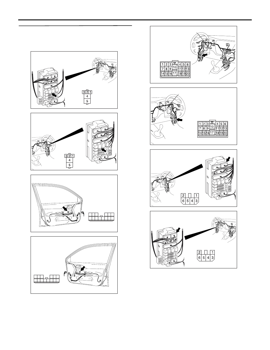
Step 12. Check the wiring harness between C-224
power window relay connector terminal No.4 and
E-05 power window main switch connector
terminal No.6.
NOTE: Prior to the wiring harness inspection, check
intermediate connectors C-17 <LH drive vehicles>,
C-110 <RH drive vehicles> and junction block con-
nector C-211, and repair if necessary.
• Check the power supply line for open circuit.
Q: Is the check result normal?
YES :
The trouble can be an intermittent
malfunction (Refer to GROUP 00, How to
Cope with Intermittent Malfunction
NO :
Repair the harness wire.
AC310448
AI
Connector: C-224 <LHD>
Junction block (front view)
Junction block side
AC310458
AG
Connector: C-224 <RHD>
Junction block (front view)
Junction block
side
AC310484
Connector: E-05 <LHD>
AD
Harness side
10
1
6
14
5
12
13
4
11
7
2
3
8
9
Front door (LH)
AC310493
Connector: E-05 <RHD>
AG
Harness side
10
1
6
14
5
12
13
4
11
7
2
3
8
9
Front door (RH)
AC310446
Connector: C-17 <LHD>
AE
AC310456
Connector: C-110 <RHD>
AH
AC310458
AI
Connector: C-211 <RHD>
Junction block (front view)
Harness side
AC310448
AJ
Connector: C-211 <LHD>
Junction block (front view)
Harness side