Mitsubishi Lancer Evolution IX. Manual - part 114
DIAGNOSTIC TROUBLE CODE PROCEDURES
SMART WIRING SYSTEM (SWS) NOT USING SWS MONITOR
54B-19
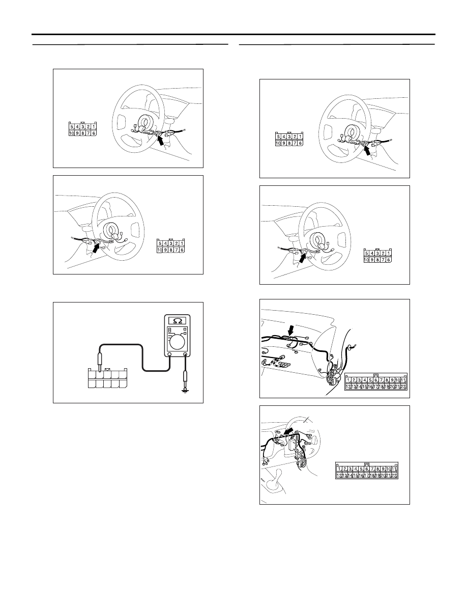
Step 5. Resistance measurement at the C-206
column switch connector
(1) Disconnect the column switch connector, and
measure at the wiring harness side.
(2) Resistance between C-206 column switch
connector terminal No.4 and body earth
OK: 2
Ω or less
Q: Is the check result normal?
YES :
Go to Step 7.
NO :
Go to Step 6.
Step 6. Check the wiring harness between C-206
column switch connector terminal No.4 and the
body earth.
NOTE:
Prior to the wiring harness inspection, check joint
connector C-06, and repair if necessary.
• Check the earth wires for open circuit.
AC310479
AD
Connector: C-206 <LHD>
Harness side
AC310481AD
Connector: C-206 <RHD>
Harness side
AC310506AK
Connector C-206
(Harness side)
10
5
6
7
9 8
3
4
2 1
AC310479
AD
Connector: C-206 <LHD>
Harness side
AC310481AD
Connector: C-206 <RHD>
Harness side
AC310452
Connector: C-06 <LHD>
AB
C-06 (GR)
AC310456
Connector: C-06 <RHD>
AB
C-06 (GR)