Mitsubishi Lancer Evolution IX. Manual - part 94
 

  Index      Mitsubishi     Mitsubishi Lancer Evolution IX - service repair manual


Search            


Content   ..  92  93  94  95   ..


Mitsubishi Lancer Evolution IX. Manual - part 94


CRANKSHAFT AND CYLINDER BLOCK

ENGINE OVERHAUL

11B-67

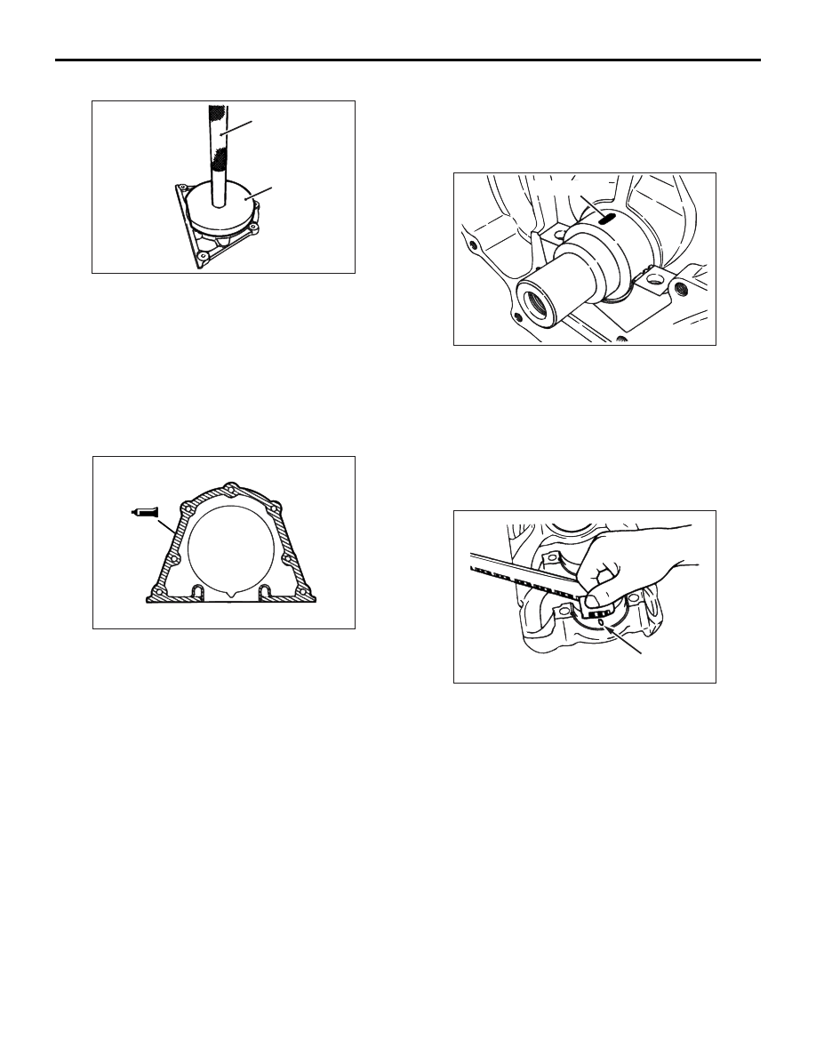
>>D<< REAR OIL SEAL INSTALLATION

Use the special tools to press-fit the rear oil seal in 
the rear oil seal case.

• Handle (MB990938)

• Crankshaft rear oil seal installer (MD998776)

>>E<< REAR OIL SEAL CASE 
INSTALLATION

1. Remove completely old FIPG remaining on the 

rear oil seal case and cylinder block.

2. Apply a bead of FIPG to the surface of the rear oil 

seal case as shown in the drawing.

Specified sealant:

Mitsubishi Genuine Part No.MD970389 or 

equivalent

3. Install the oil seal into the cylinder block after 

applying an appropriate amount of engine oil to 
the entire circumference of its lip portion.

4. Install the rear oil seal case by tightening its bolts 

to 11 

± 1 N⋅m.

INSPECTION

M1113008800485

CRANKSHAFT OIL CLEARANCE 
(PLASTIGAGE METHOD)

This plastigage method is recommended as a sim-
plest way of measuring the crankshaft oil clearance.

Measure the crankshaft oil clearance using a plasti-
gage as follows:
1. Wipe off oil from the crankshaft journal surface 

and the crankshaft bearing inner surface.

2. Install the crankshaft.

3. Cut a piece of plastigage whose length is 

equivalent to the width of the bearing and place it 
on the crankshaft journal in parallel with its axis.

4. Install the crankshaft bearing cap carefully and 

tighten the bolts to the specified torque of 25 

± 2 

N

⋅m + 90° to 100°.

5. Remove the bolts, then remove the crankshaft 

bearing cap carefully.

6. Measure the largest width of the crushed 

plastigage using the ruler printed on the bag of the 
plastigage.

Standard value: 0.03 

 0.04 mm

Limit: 0.1 mm

CYLINDER BLOCK

1. Visually check the cylinder block for scratches, 

rust, and any other corrosion. Also check it for 
cracks using a flaw detecting penetrant.
If any defect is evident, replace the cylinder block.

AK202827

MB990938

MD998776

AC

AK202824AB

AK202826

Plastigage

AB

AK202822

Plastigage

AB

CRANKSHAFT AND CYLINDER BLOCK

ENGINE OVERHAUL

11B-68

2. Use a straightedge and thickness gauge to check 

the cylinder block top surface for warp.
Make sure that the surface is free from remaining 
gasket material and other foreign matter.

Standard value: 0.05 mm
Limit: 0.1 mm

3. If the distortion is excessive, correct within the 

allowable limit or replace.

Grinding limit: 0.2 mm 
*Includes/combined with cylinder head 
grinding
Cylinder block height (when new): 284 mm

4. Check cylinder walls for scratches and seizure.

If defects are evident, rebore to oversize or 
replace the cylinder block.

5. Use a cylinder gauge to measure the cylinder 

bore diameter and taper.
If the cylinder is worn badly, rebore it to an 
oversize and replace the piston and piston rings 
with ones matched with the new bore size.

Standard value: 85.0 mm
Taper: 0.01 mm

BORING CYLINDERS

1. Select an oversize of the pistons to be used 

based on the largest of the cylinder bores.

2. Oversize pistons are available in two oversizes: 

0.50 mm and 1.00 mm. Bore each cylinder to a 
size that provides the standard clearance when 
combined with the selected piston. The reference 
position for piston diameter measurement is as 
shown in the drawing.

3. Based on the piston diameter measurement, 

calculate the boring finish dimension.

• Boring finish dimension = [Piston diameter] + 

[0.02 

− 0.04 mm (clearance between piston and 

cylinder)] 

− [0.02 mm (honing margin)]

CAUTION

To prevent deformation of cylinder block that 
would result from the heat generated by boring, 
bore the cylinders in the following sequence: No. 

 No. 4  No. 1  No. 3.

4. Bore all the cylinders to the calculated boring 

finish dimension.

5. Hone the bored cylinders to the final finish 

dimension (piston diameter + clearance between 
piston and cylinder).

6. Check the clearance between the piston and 

cylinder.

Standard value: 0.02 

 0.04 mm

AK401851

AK202731

12 mm

AB

Center

Bottom

AK203804

Piston diameter

12.5 mm

AC

NOTES


Content   ..  92  93  94  95   ..