Mitsubishi Lancer Evolution IX. Manual - part 84
 

  Index      Mitsubishi     Mitsubishi Lancer Evolution IX - service repair manual


Search            


Content   ..  82  83  84  85   ..


Mitsubishi Lancer Evolution IX. Manual - part 84


TIMING BELT

ENGINE OVERHAUL

11B-27

>>N<< SEMICIRCULAR PACKING 
INSTALLATION

1. Remove thoroughly the old sealant and FIPG 

remaining on the semicircular packing, cylinder 
head, and rocker cover.

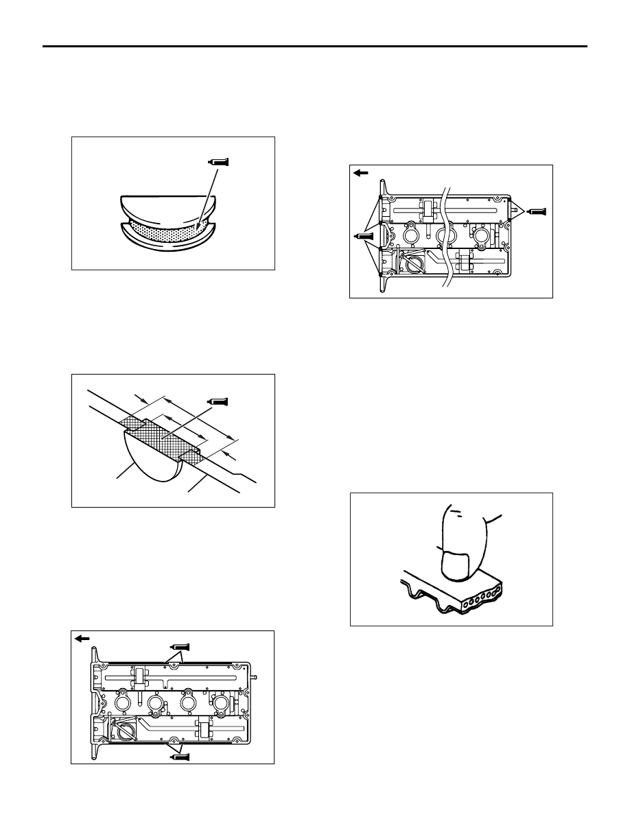
2. Apply sealant to the surface indicated in the 

drawing of the semicircular packing.

Specified sealant:

3M ATD No.8660 or equivalent

3. Install the semicircular packing on the cylinder 

head.

4. Apply sealant to the area indicated in the drawing 

of the semicircular packing and cylinder head.

Specified sealant:

3M ATD No.8660 or equivalent

>>O<< ROCKER COVER/ROCKER 
COVER GASKET "A" INSTALLATION

1. Apply beads of FIPG on the surfaces of the rocker 

cover indicated in the drawing.

Specified sealant:

Mitsubishi Genuine Part No.MD970389 or 

equivalent

2. Install the rocker cover gasket "A" on the rocker 

cover before the FIPG hardens.

3. Apply beads of FIPG to the surfaces of the rocker 

cover indicated in the drawing.

Specified sealant:

Mitsubishi Genuine Part No.MD970389 or 

equivalent

4. Install the rocker cover on the cylinder head 

before the FIPG hardens.

INSPECTION

M1113002000500

TIMING BELT

Check closely the entire timing belt.
Replace it if any of the following conditions is found.

1. Hardened back side rubber.

Back side surface is glossy, lacking in elasticity, 
and so hard that no impression is left when 
pressed with fingernail.

AK202860AB

AK304411AB

10 mm

10 mm

Semicircular 
packing

Cylinder head

AK304203AB

Timing belt side

AK304204AB

Timing belt side

AK202794

TIMING BELT

ENGINE OVERHAUL

11B-28

2. Cracks in back rubber surface.
3. Cracks in canvas.
4. Cracks in tooth roots.
5. Cracks in belt sides.

6. Abnormally worn belt sides;

NOTE: belt sides are normal if they have 
“knife-cut” surfaces.

7. Badly worn teeth.
Initial stage: Canvas is worn (canvas fiber is fluffy; 
teeth look whitish due to worn-out rubber; canvas 
texture is unclear)
Second stage: Canvas is lost and rubber is exposed 
(tooth width narrows down)
8. Missing tooth.

AUTO-TENSIONER

1. Check the auto-tensioner for leaks from the 

sealed sections. 
Replace it if leaky.

2. Check the rod end for wear and other damage.

Replace the auto-tensioner if the rod is badly 
worn or damaged.

3. Measure the extension length of the rod.

If it is not within the standard value range, replace 
the auto-tensioner.

Standard value: 12 mm

4. Press the rod with a force of 98 to 196 N and 

measure the amount of retraction. If the 
measurement exceeds the standard value, 
replace the auto-tensioner.

Standard value: 1 mm maximum

AK202793

Cracks

Peeling of canvas

Cracks in tooth roots

Cracks

AB

Cracks in sides

AK202795

Rounded edge

Abnormal wear 
(Fluffy strand)

AB

AK202796

Missing 
Tooth

Canvas lost and 
rubber exposed

AB

AK301307AD

12 mm 

AK301308AE

98 to 196 N

Movement

FUEL AND EMISSION PARTS

ENGINE OVERHAUL

11B-29

FUEL AND EMISSION PARTS

REMOVAL AND INSTALLATION

M1113002200485

AK203808

20 ± 2 N·m 

19 ± 3 N·m

8.8 ± 2.0 N·m

1

10

6

15

3

5

12

8

9

AE

12 ± 1 N·m

2

4

7

13

14

11

Removal steps 

1. Throttle body

>>

C

<< 2. Throttle body gasket

3. EGR valve
4. EGR valve gasket
5. Fuel hose

>>

B

<< 6. Fuel pressure regulator

7. O-ring
8. Injector and delivery pipe

9. Insulator
10. Fuel return pipe
11. Insulator

>>

A

<< 12. Injector

13. O-ring
14. Grommet
15. Delivery pipe

Removal steps (Continued)

FUEL AND EMISSION PARTS

ENGINE OVERHAUL

11B-30

INSTALLATION SERVICE POINTS
>>A<< INJECTOR INSTALLATION

1. Apply a thin coat of engine oil to a new O-ring.

CAUTION

Prevent engine oil from getting into the delivery 
pipe.
2. Insert the injector into the delivery pipe while 

turning it in both directions carefully not to 
damage the O-ring.

3. Check that the injector turns smoothly. If it does 

not, the O-ring may be jamming, so remove the 
injector and check the O-ring for damage. If the 
O-ring is intact, insert the injector into the delivery 
pipe and check it for smooth rotation again.

>>B<< FUEL PRESSURE REGULATOR 
INSTALLATION

1. Apply a thin coat of engine oil to a new O-ring.

CAUTION

Prevent engine oil from getting into the delivery 
pipe.
2. Insert the fuel pressure regulator into the delivery 

pipe while turning it in both directions carefully not 
to damage the O-ring.

3. Check that the fuel pressure regulator turns 

smoothly. If it does not, the O-ring may be 
jamming, so remove the fuel pressure regulator 
and check the O-ring for damage. If the O-ring is 
intact, insert it into the delivery pipe and check it 
for smooth rotation again.

>>C<< THROTTLE BODY GASKET 
INSTALLATION

Install the throttle body gasket with its tab located as 
shown in the drawing.

AK203932AG

Tab


Content   ..  82  83  84  85   ..