Mitsubishi Lancer Evolution IX. Manual - part 76
 

  Index      Mitsubishi     Mitsubishi Lancer Evolution IX - service repair manual


Search            


Content   ..  74  75  76  77   ..


Mitsubishi Lancer Evolution IX. Manual - part 76


HOW TO READ WIRING DIAGRAMS

GENERAL <ELECTRICAL>

00E-7

Item

No.

Connector/Earthing

Symbol

Contents

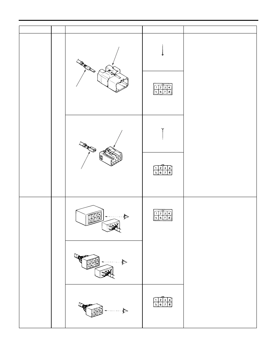
Connector 
and terminal 
marking

1

ACX01251AE

Male terminal

Male connector

ACX01252AD

Male terminal

The male and female terminals 
are indicated as shown. The 
connector with male terminal(s) 
is called as male connector and 
indicated by two connector 
contour lines, while the 
connector with female 
terminal(s) is called as female 
connector and indicated by 
single connector contour line.

ACX01253 AI

Male connector

ACX01254 AD

Female terminal

Female connector

ACX01255AD

Female terminal

ACX01256 AH

Female connector

Connector 
symbol 
marking

2

ACX01257AD

Device

ACX01253

The symbol indicates the 
connector is viewed as shown. 
At a device connection, the 
connector symbol on the device 
side is shown. For an 
intermediate connector, the 
male connector symbol is 
shown. For spare connectors 
and check connectors, no 
device is connected, and so the 
harness-side connector symbol 
is shown for these connectors.
However, a diagnosis connector 
is exceptional. 

ACX01258AD

Intermediate connector

ACX01816

Spare connector, check connector

AD

ACX01256

HOW TO READ WIRING DIAGRAMS

GENERAL <ELECTRICAL>

00E-8

Connector 
connection 
marking

3

ACX01260 AD

Direct connection type

ACX01261

Connection between a device 
and the harness is either by 
direct insertion in the device 
(direct connection type) or by 
connection with a harness 
connector furnished on the 
device side (harness 
connection type). The two types 
are indicated as illustrated.

4

ACX01262 AD

Harness connection type

ACX01263

5

ACX01264AD

Intermediate connector

ACX01265

Earth 
marking

6

AC208448

AB

Body earth

ACX01274

Earthing is either by body earth, 
device earth or control unit 
interior earth. These are 
indicated as illustrated.

7

AC208449

AB

Device earth

ACX01276

8

AC208450

AB

Earth in control unit

ACX01278

Item

No.

Connector/Earthing

Symbol

Contents

HOW TO READ WIRING DIAGRAMS

GENERAL <ELECTRICAL>

00E-9

WIRE COLOUR CODE

M1001008000195

Wire colours are identified by the following colour 
codes.

Code

Wire colour

Code

Wire colour

Code

Wire colour

Code

Wire colour

B

Black

L

Blue

PU

Purple

V

Violet

BR

Brown

LG

Light green

R

Red

W

White

G

Green

O

Orange

SB

Sky blue

Y

Yellow

GR

Grey

P

Pink

SI

Silver

ACX01279 AE

<F>

1.25

G

B

1

2

3

4

Example:

If a cable has two colours, the first of the two colour 
code characters indicates the basic colour (colour of 
the cable coating) and the second indicates the 
marking colour.

No.

Meaning

1

<F>: Flexible wire
<T>: Twisted wire

2

Wire size (mm

2

)*

3

Basic colour (colour of the cable coating)

4

Marking colour

NOTE: 


*: No code indicates 0.5 mm

2

. Cable colour code in 

parentheses indicates 0.3 mm

2

.

ABBREVIATION SYMBOLS

M1001008100255

The abbreviation symbols used in wiring diagrams are defined below.

1. For system name

Abbreviation 
symbol

Meaning

Abbreviation 
symbol

Meaning

ABS

Anti-skid braking system

J/C

Joint connector

ACD

Active centre differential

M/T

Manual transmission

AYC

Active yaw control

MPI

Multi-point injection

DOHC

Double overhead camshaft engine

SRS

Supplemental restraint system

J/B

Junction block

HOW TO READ WIRING DIAGRAMS

GENERAL <ELECTRICAL>

00E-10

2. For combination meter

Abbreviation 
symbol

Meaning

Abbreviation 
symbol

Meaning

ABS

Anti-skid braking system warning 
lamp

POSITION

Position lamp indicator lamp

BEAM

High beam indicator lamp

REAR FOG

Rear fog lamp indicator lamp

BRAKE

Brake warning lamp

SPEED

Speedometer

CHECK 
ENGINE

Check engine warning lamp

SRS

Supplemental restraint system 
warning lamp

CHG

Charging warning lamp

T/GA

Engine coolant temperature gauge

DOOR

Door-ajar warning lamp

TACHO

Tachometer

F/GA

Fuel gauge

TRIP

Tripmeter

FUEL

Low fuel warning lamp

TARMAC

Active centre differential mode 
indicator lamp

LCD

Liquid crystal display

GRAVEL

ODO

Odometer

SNOW

OIL

Oil pressure warning lamp

TURN (LH)

Turn signal indicator lamp, hazard 
indicator lamp

OIL LEVEL

Engine oil level warning lamp

TURN (RH)

3. For switches and relays

Name of switches 
and relays

Abbreviation 
symbols

Operation

Blower switch

LO

Blower operates at low speed

ML

Blower operates at medium low speed

MH

Blower operates at medium high speed

HI

Blower operates at high speed

Dimmer passing switch LO

Low beams ON

HI

High beams ON

PASS

High beams ON

Door lock actuator

LOCK

Door lock

UNLOCK

Door unlock

Front room lamp, rear 
room lamp

DOOR

Room lamp ON when a door is open

Headlamp leveling 
switch

1

Lower the low-beam in one step

2

Lower the low-beam in two steps

3

Lower the low-beam in three steps

4

Lower the low-beam in four steps


Content   ..  74  75  76  77   ..