Mitsubishi Lancer Evolution 8. Manual - part 147


  Index      Mitsubishi     Mitsubishi Lancer Evolution 8 - service repair manual


Search            


Content   ..  145  146  147  148   ..


Mitsubishi Lancer Evolution 8. Manual - part 147


SWS – TROUBLESHOOTING

54B-111

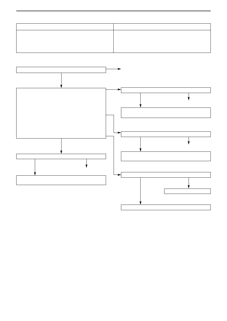
Check connector C-224

Check connector C-210

Check the harness between the ETACS-ECU and the
ignition switch (ACC), and repair

Check connectors C-211, C-32

Check the harness between the ETACS-ECU and the
battery, and repair.

Check connector C-210

Check the harness between the ETACS-ECU and the
ignition switch (IG1), and repair

Confirm the trouble symptoms 

Replace the ETACS-ECU 

Transient problem

Measure at the ETACS-ECU C-224
• Detach the connector and measure at the junction box

side

• Ignition switch: ON
(1) Voltage between 20 & body earth

OK: Battery voltage

(2) Voltage between 8 & body earth

OK: Battery voltage

(3) Voltage between 4 & body earth

OK: Battery voltage

(4) Voltage between 18 & body earth

OK: Battery voltage

Inspection procedure R-19

Generic fuse No.17 load use signal not detected

Probable Cause

The generic fuse No.17 load signal is used to determine the
interior light cut-off function, and if there is a problem in this
signal, then the following functions will cease to work properly.
• Ignition key cylinder illumination light
• Interior light

• Fault in ETACS-ECU 
• Fault in harness or connectors

OK

(3), (4) NG

OK

NG

Repair

NG

(1) NG

(2) NG

OK

OK

NG

NG

OK

OK

NG

Repair

Repair

Repair

SWS – TROUBLESHOOTING

54B-112

11.  Chart of terminal voltages

11-1 ETACS-ECU

Note :
Terminals No. 1 to 20 cannot be measured as the ETACS-ECU is installed directly on the junction box, and they are listed for
reference.

Terminal
No.

Check Item

Check ConditionsNormal State

1

Electric window relay output

Electric windows operable

Battery voltage

2

Central door lock power supply (battery
voltage)

Any

Battery voltage

3

Earth (for ECU)

Any

0V

4

Ignition switch (ACC)

Ignition switch : ACC

Battery voltage

5

Interior light output

Interior lights switched on

2V or lower

6

Interior light power supply (battery
voltage)

Any (Interior light cut-off function not
operating)

Battery voltage

7

All door switch input

Any door switch : ON (door open)

0V

8

Ignition switch (IG1) power supply

Ignition switch : ON

Battery voltage

9

RH Turn indicator light output

RH Turn indicator light on

Battery voltage

10

Driver’s door switch input

Driver’s door switch : ON (door open)

0V

11

Hazard light power supply (battery
voltage)

Any

Battery voltage

12

Central door locking (lock) output

Door lock actuator operating (lock
operation)

Battery voltage

13

Central door locking (unlock) output
(except driver’s)

Door lock actuator operating (unlock
operation)

Battery voltage

14

LH Turn indicator light output

LH Turn indicator light on

Battery voltage

15
16

Rear wiper output

Rear wiper operating

Battery voltage

17

Rear wiper automatic stop signal input

Rear wiper operating

Battery voltage

18

Ignition switch (ACC) power supply

Ignition switch : ACC

Battery voltage

19
20

Battery voltage (for ECU)

Any

Battery voltage

21
22

Central door locking (unlock) output (for
driver’s door)
(Vehicle fitted with keyless entry)

Door lock actuator operating (unlock
operation)

Battery voltage

23

Rear washer output

Rear washer operating

Battery voltage

24

Motorised remote control mirror switch
(fold / return switch) input

Motorised remote control mirror
switch (fold / return) switch : ON

0V

25 – 29
30

Key reminder switch input

Key reminder switch : ON
(Ignition key removed)

0V

31

Motorised foldable door mirror output

Motorised foldable door mirrors
operating (fold operation)

Battery voltage

SWS – TROUBLESHOOTING

54B-113

Terminal
No.

Check Item

Check ConditionsNormal State

32 – 34
35

Driver’s door lock actuator (lock switch)
input

Driver’s door lock: when locked

0V

36

Driver’s door lock actuator (unlock switch)
input

Driver’s door lock: when unlocked

0V

37, 38
39

Reversing light switch input

Shift lever : R
Ignition switch : ON

Battery voltage

40

Motorised foldable door mirror output

Motorised foldable door mirror
operating (folding operation)

12V

41 – 43
44

Horn output

Alarm operating (horn output)

0V

Diagnosis being output(MUT-II/III
connection or diagnosis connector
No.1 earthed to body)

0 – 12V (pulse
signal)

51

Diagnosis output or input check signal
output

When input check is being output

0V, 12V
(changing input
signal)

52
53

Door ajar indicator light output

Door ajar indicator light switched on

0V

54

Fog light switch input

Fog light switch : ON

0V

55

Hazard light switch input

Hazard light switch : ON

0V

56

Earth (for sensor)

Any

0V

57,58
59

SWS communications line

Any

0 – 12V (pulse
signal)

60-62
63

Vehicle speed signal input

Vehicle travelling

0 – 12V (pulse
signal)

64, 65
66

Intermittent windscreen wiper volume
input

Ignition switch : ACC
Volume position : FAST 

 SLOW

 2.5 V

67

Diagnosis control input

MUT-II/III connected

0V

68

SWS request signal output

Any

0 – 12V (pulse
signal)

69

Ignition key cylinder illumination light
output

Ignition key cylinder illumination
switched on

2V or lower

70
71

Interior light power supply

Any (Interior light cut-off function not
operating)

Battery voltage

72-74

SWS – TROUBLESHOOTING

54B-114

11-2 Column switch

11-3  Front ECU

Note : The front ECU is installed directly on the relay box, and cannot be measured. The terminals are listed here for
reference.

Terminal
No.

Check Item

Check ConditionsNormal State

1

Battery power supply

Any

Battery voltage

2

SWS request signal input

Any

0 – 12 V (pulse
signal)

3

SWS communications line

Any

0 – 12 V (pulse
signal)

4

Earth

Any

0V

5
6

Intermittent windscreen wiper volume
output

Ignition switch : ACC
Volume position : FAST 

 SLOW

 2.5V

7
8

Windscreen wiper switch back-up output

Low speed windscreen wiper or High
speed windscreen wiper : ON

0V

9

Ignition switch (IG1) power supply

Ignition switch : ON

Battery voltage

10

Head light switch back-up output

Head light switch : ON

0V

Terminal
No.

Check Item

Check ConditionsNormal State

1

Fog light output

Fog lights switched on

2

Head light (high beam) output

Head lights (high beam) switched on

Battery voltage

3, 4

Battery power supply (for head light)

Any

Battery voltage

5

Battery power supply (for tail light)

Any

Battery voltage

6

Head light (low beam) output

Head lights (low beam) switched on

Battery voltage

7

Battery power supply (for ECU)

Any

Battery voltage

8

Tail light output

Tail lights switched on

Battery voltage

9 – 11
21

Windscreen washer output

Windscreen washer operating

Battery voltage

22

SWS communications line

Any

0 – 12V (pulse
signal)

23

Windscreen wiper automatic stop signal
input

Windscreen wiper operating

Battery voltage

24

Ignition switch (ACC) power supply

Ignition switch : ACC

Battery voltage

25

Head light switch back-up input

Head light switch : ON

0V

26

Windscreen wiper switch back-up input

Low-speed windscreen wiper switch
or high-speed windscreen wiper
switch : ON

0V

27

Windscreen wiper (LO speed) output

Windscreen wiper operating
(Low speed operation)

Battery voltage

28

Windscreen wiper (HI speed) output

Windscreen wiper operating
(High speed operation)

Battery voltage


Content   ..  145  146  147  148   ..