Mitsubishi Lancer Evolution 8. Manual - part 38
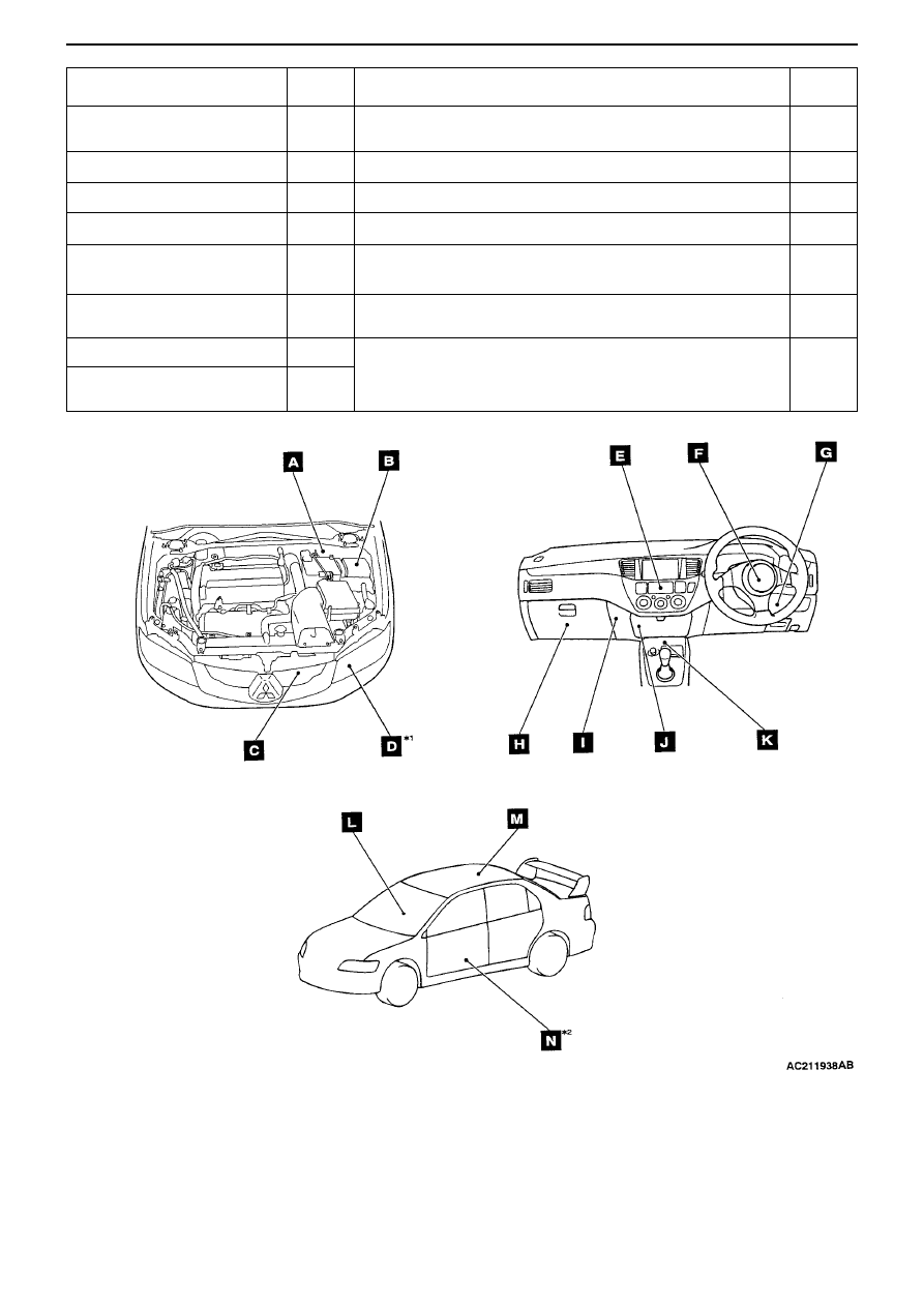
COMPONENT INSTALLATION POSITIONS - ECU
2-2
Notes:
• The *
1
symbol indicates RH fitting as well.
• The *
2
symbol indicates rear door (LH, RH) fitting as well.
Name
Symbol Name
Symbol
A/C-ECU <vehicle fitted with
fully automatic A/C>
E
Sunroof motor Assy.(built in ECU)
M
ABS-ECU
A
Electric window subswitch (built in ECU)
N
ETACS-ECU
G
Electric window main switch (built in ECU)
L
SRS-ECU
K
Front ECU
B
4WD-ECU
J
Blower pulse controller
<vehicle fitted with fully automatic A/C>
H
Immobiliser ECU
I
Headlight Assy.(built in discharge ECU)
<vehicle fitted with discharge type headlights>
D
Engine ECU
I
Radiator fan controller
C
Column switch (built in
column ECU)
F
M3020000500180