Mitsubishi Eclipse / Eclipse Spyder (2000-2002). Service and repair manual - part 699
 

  Index      Mitsubishi     Mitsubishi Eclipse / Eclipse Spyder (2000-2002). Service and repair manual


Search            


Content   ..  697  698  699  700   ..


Mitsubishi Eclipse / Eclipse Spyder (2000-2002). Service and repair manual - part 699


BLOWER ASSEMBLY AND RESISTOR

TSB Revision

HEATING AND AIR CONDITIONING

55-33

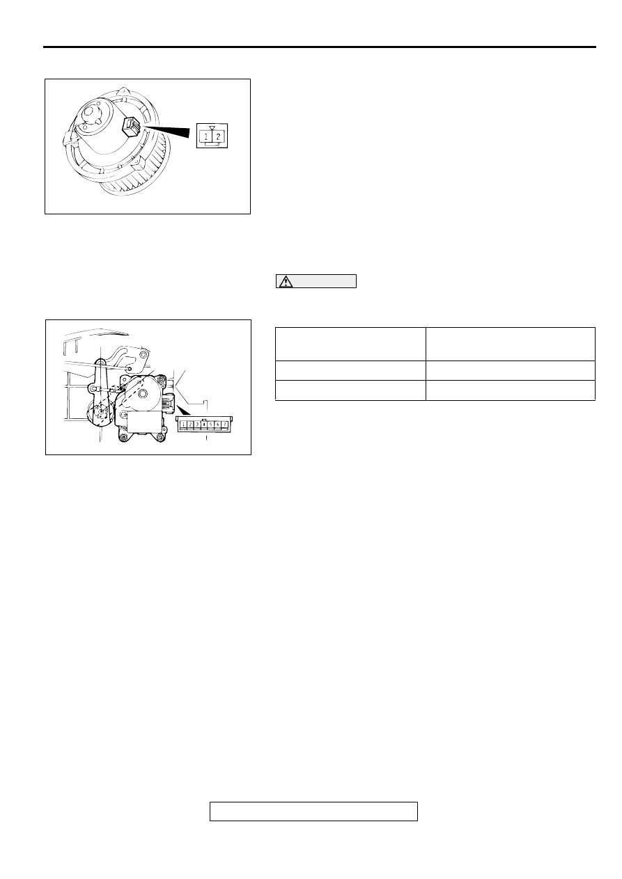
BLOWER FAN AND MOTOR CHECK

When battery voltage is applied between the terminals, check 
that the motor operates. Also, check that there is no abnormal 
noise.

INSIDE/OUTSIDE AIR CHANGEOVER DAMPER 
MOTOR CHECK

CAUTION

Cut off the battery voltage when the damper is in the 
inside/outside air position.

AC001403AB

BATTERY CONNECTION 
TERMINALS 

LEVER POSITION

1-7

Move to the outside air position

1-5

Move to the inside air position

AC001404

AC001404AB

INSIDE AIR POSITION

OUTSIDE AIR
POSITION

COMPRESSOR ASSEMBLY AND TENSION PULLEY

TSB Revision

HEATING AND AIR CONDITIONING

55-34

CO M PR ESSO R  A SSEM BLY AN D TEN SIO N PULLEY

M1552004100041

REMOVAL AND INSTALLATION

Pre-removal Operation

Refrigerant Discharging (Refer to 

P.55-21

.)

Post-installation Operation

Drive Belt Tension Adjustment (Refer to GROUP 
00E, Maintenance Service 

 Drive Belt 

P.00-40

.)

Refrigerant Charging (Refer to 

P.55-21

.)

AC001405

1

2

3

3

4

5

6

<2.4L ENGINE>

COMPRESSOR OIL:
SUN PAG 56

N

N

25 ± 4 N·m
18 ± 4 ft-lb

1

2

3

4

5

6

<3.0L ENGINE>

AB

25 ± 4 N·m
18 ± 4 ft-lb

PIPING CONNECTOR

REMOVAL STEPS

CONDENSER FAN MOTOR 
<3.0L ENGINE> (REFER TO 

P.55-40

.)

<<A>>

1.

DRIVE BELT

<<B>>

2.

DISCHARGE HOSE AND 
SUCTION HOSE

3.

O-RING

<<C>>

>>A<<

4.

COMPRESSOR

5.

TENSION PULLEY

6.

COMPRESSOR BRACKET

REMOVAL STEPS (Continued)

COMPRESSOR ASSEMBLY AND TENSION PULLEY

TSB Revision

HEATING AND AIR CONDITIONING

55-35

REMOVAL SERVICE POINTS

<<A>> DRIVE BELT REMOVAL
1. Loosen the nut "A" for holding.

2. Loosen the bolt "B" for adjustment.

3. Remove the drive belt.

<<B>> DISCHARGE HOSE AND SUCTION HOSE 
DISCONNECTION

CAUTION

Seal the hoses completely, otherwise the compressor oil 
and receiver will absorb water vapor easily, possibly 
damaging the compressor and deteriorating performance.
Plug the disconnected hose and compressor nipple to prevent 
foreign matter from getting into them.

<<C>> COMPRESSOR REMOVAL
When removing the compressor, be careful not to spill the 
compressor oil.

INSTALLATION SERVICE POINT

>>A<< COMPRESSOR INSTALLATION
If a new compressor is installed, first adjust the amount of oil 
according to the procedures described below, and then install 
the compressor.

1. Measure the amount [X cm

3

 (X floz)] of oil within the 

removed compressor.

2. Drain (from the new compressor) the amount of oil 

calculated according to the following formula, and then 
install the new compressor.
New compressor oil amount

100 cm

3


 X cm

3

 = Y cm

3

 (3.4 floz 

 X floz = Y floz) 

NOTE: Y cm

3

 (Y floz) indicates the amount of oil in the 

refrigerant line, the condenser, the evaporator, etc.

AC001406AB

A

B

<3.0L ENGINE>

A

B

<2.4L ENGINE>

A

VIEW A

COMPRESSOR ASSEMBLY AND TENSION PULLEY

TSB Revision

HEATING AND AIR CONDITIONING

55-36

NOTE: When replacing the following parts at the same times 
as the compressor, subtract the rated oil amount of the each 

part from Y cm

3

 (Y floz) and discharge from the new 

compressor.

Quantity:

••••

Evaporator: 60 cm

3

 (2.0 floz)

••••

Condenser: 15 cm

3

 (0.5 floz)

••••

Suction hose: 10 cm

3

 (0.3 floz)

••••

Receiver: 10 cm

3

 (0.3 floz) 

INSPECTION

M1552009300040

REFRIGERANT TEMPERATURE SWITCH CHECK

When the A/C is off, check that there is continuity between the 
refrigerant-temperature switch terminals. If not, replace the 
switch.

COMPRESSOR MAGNETIC CLUTCH OPERATION 
INSPECTION

M1552008500096

Connect the battery (+) terminal to the compressor magnetic 
clutch connector terminal 3, and ground the battery (

) terminal 

to the body of the compressor. The condition is normal if the 
sound of the magnetic clutch (click) can be heard.

AC001407

REFRIGERANT-
TEMPERATURE
SWITCH TERMINALS

AB

AC001367

1 2

3 4

AB

<2.4L ENGINE>

<3.0L ENGINE>

MAGNETIC CLUTCH
CONNECTOR

MAGNETIC CLUTCH
CONNECTOR


Content   ..  697  698  699  700   ..