Mitsubishi Eclipse / Eclipse Spyder (2000-2002). Service and repair manual - part 683
 

  Index      Mitsubishi     Mitsubishi Eclipse / Eclipse Spyder (2000-2002). Service and repair manual


Search            


Content   ..  681  682  683  684   ..


Mitsubishi Eclipse / Eclipse Spyder (2000-2002). Service and repair manual - part 683


SRS AIR BAG DIAGNOSIS

TSB Revision

SUPPLEMENTAL RESTRAINT SYSTEM (SRS)

52B-59

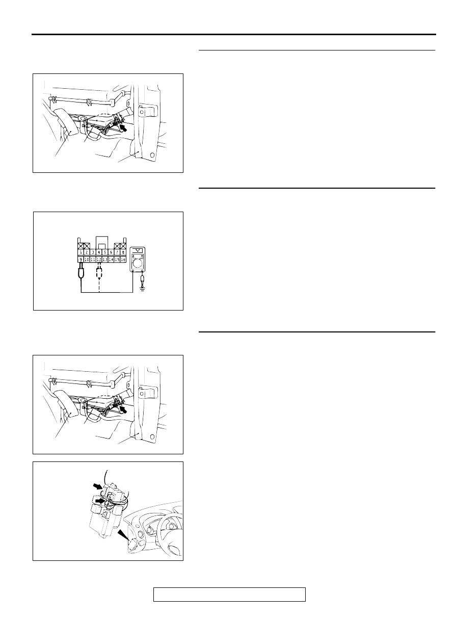
STEP 2. Check the harness wires between SRS-ECU 
connector C-72 and ground.
Q: Is the harness wires between SRS-ECU connector C-72 

and ground in good condition?
YES : 
Go to Step 5.
NO :  Repair them. Then go to Step 5.

STEP 3. Check the ignition switch (IG1) line at the SRS-
ECU connector C-72 by backprobing.
(1) Do disconnect the connector C-72.
(2) Turn the ignition switch to "ON" position.
(3) Measure the voltage between terminal 9 and the ground.

Voltage should be 9 volts or more

(4) Measure the voltage between terminal 12 and the ground 

by backprobing.

Voltage should be 9 volts or more

Q: Is the voltage between terminal 9,12 and the ground 9 V 

or more?
YES : 
Go to Step 5.
NO :  Go to Step 4.

STEP 4. Check the harness wires between ignition switch 
(IG1) and SRS-ECU connector C-72.
NOTE: After inspecting intermediate connectors C-101, C-107 
inspect the wiring harness. If intermediate connectors C-101, 
C-107 are damaged, repair or replace them. Refer to GROUP 
00E, Harness Connector Inspection 

P.00E-2

Then go to Step 

6.

Q: Are the harness wires between ignition switch (IG1) and 

SRS-ECU connector C-72 in good condition?
YES : 
Go to Step 6.
NO :  Repair them. Then go to Step 6.

AC000358AD

SRS-ECU

ACCELERATOR PEDAL

CENTER REINFORCEMENT(LH)

CONNECTOR: C-72

AC000367AC

C-72 CONNECTOR HARNESS SIDE VIEW

AC000358AD

SRS-ECU

ACCELERATOR PEDAL

CENTER REINFORCEMENT(LH)

CONNECTOR: C-72

AC000366AC

CONNECTOR: C-101, C-107

C-101

C-107

JUNCTION
BLOCK
(FRONT VIEW)

SRS AIR BAG DIAGNOSIS

TSB Revision

SUPPLEMENTAL RESTRAINT SYSTEM (SRS)

52B-60

STEP 5. Check the harness wires between SRS-ECU 
connector C-72 and data link connector C-29.
Q: Are the harness wires between SRS-ECU connector C-

72 and data link connector C-29 in good condition?
YES : 
Replace the SRS-ECU. Refer to 

P.52B-66

Then go 

to Step 6.

NO :  Repair them. Then go to Step 6.

STEP 6. Check symptoms.

Q: Does the scan tool communicate normally with the SRS 

system?
YES : 
This diagnosis is complete.(If no malfunctions are not 

found in all steps, an intermittent malfunction is 
suspected. Refer to GROUP 00, How to Use 
Troubleshooting/Inspection Service Points 

 How to 

Cope with Intermittent Malfunction 

P.00-6

.)

NO :  There is no action to be taken

AC000358AD

SRS-ECU

ACCELERATOR PEDAL

CENTER REINFORCEMENT(LH)

CONNECTOR: C-72

AC000800AC

CONNECTOR: C-29

COMBINATION METER

SPECIAL TOOLS

TSB Revision

SUPPLEMENTAL RESTRAINT SYSTEM (SRS)

52B-61

SPECIA L TO O LS

M1524000700077

TOOL

TOOL NUMBER AND 
NAME

REPLACED BY MILLER 
TOOL NUMBER

APPLICATION

MB991502 
Scan tool (MUT-II)

MB991496-OD

Reading diagnostic trouble 
codes

Erasing diagnostic trouble 
codes

Reading vehicle data for a 
specific period

Reading erase times (Refer to 
MUT-II operating instructions)

MB991223 
A: MB991219 
B: MB991220 
C: MB991221 
D: MB991222 
Harness set 
A: Test harness 
B: LED harness 
C: LED harness adapter 
D: Probe

-

Checking the continuity and 
measuring the voltage at the 
SRS-ECU harness connector

MB991613 
SRS check harness

MB991613

Checking the SRS electrical 
circuitry with a digital multi-meter

MB990803 
Steering wheel puller

General service tool

Removal of steering wheel

MR372530 
SRS air bag adapter 
harness A

General service tool

Deployment of air bag module 
(Driver's side) inside the vehicle

MB686560 
SRS air bag adapter 
harness B

General service tool

Deployment of air bag module 
(Front passenger's side) inside 
the vehicle

Deployment of air bag module 
(Front passenger's side) 
outside the vehicle

MR203491 or MB628919 
SRS air bag adapter 
harness C

General service tool

Deployment of air bag module 
(Driver's side) outside the vehicle

B991502

MB991223

A

D

C

B

AG

MB991613

MB990803

MR372530

MB686560

MB628919

TEST EQUIPMENT

TSB Revision

SUPPLEMENTAL RESTRAINT SYSTEM (SRS)

52B-62

TEST EQ U IPM ENT

M1524000800074

SR S M A IN TEN A N C E

M1524003900070

The SRS must be inspected by an authorized dealer up to 10 
years after the date of vehicle registration. (Refer to GROUP 
00, Maintenance Service 

 SRS Maintenanc

P.00-55

.)

PO ST-C O LLISIO N  D IA G N O SIS

M1524001100078

To inspect and service the SRS after a collision (whether or not 
the air bags have deployed), perform the following steps.

SRS-ECU MEMORY CHECK

Required Special Tool:

MB991502: Scan tool (MUT-II)

CAUTION

To prevent damage to scan tool MB991502, always turn the 
ignition switch to "LOCK" (OFF) position before 
connecting or disconnecting scan tool MB991502.
1. Connect scan tool MB991502 to the data link connector (16-

pin).

NOTE: If the battery power supply has been disconnected or 
disrupted by the collision, scan tool MB991502 cannot 
communicate with the SRS-ECU. Check the battery then 
check and, if necessary, repair the front wiring harness and 
the body wiring harness before proceeding.

2. Read (and write down) all displayed DTC. (Refer to 

P.52B-

18

.)

3. Read the data list (fault duration and how many times 

memories are erased) using scan tool MB991502.

TOOL

NAME

USE

Digital multi-meter Use a multi-meter for 
which the maximum test current is 2 mA or 
less at the minimum range of resistance 
measurement

Checking the SRS electrical circuitry with 
SRS check harness

AC000019AB

AC000356AB

16PIN

MB991502


Content   ..  681  682  683  684   ..