Mitsubishi Eclipse / Eclipse Spyder (2000-2002). Service and repair manual - part 677
 

  Index      Mitsubishi     Mitsubishi Eclipse / Eclipse Spyder (2000-2002). Service and repair manual


Search            


Content   ..  675  676  677  678   ..


Mitsubishi Eclipse / Eclipse Spyder (2000-2002). Service and repair manual - part 677


SRS AIR BAG DIAGNOSIS

TSB Revision

SUPPLEMENTAL RESTRAINT SYSTEM (SRS)

52B-35

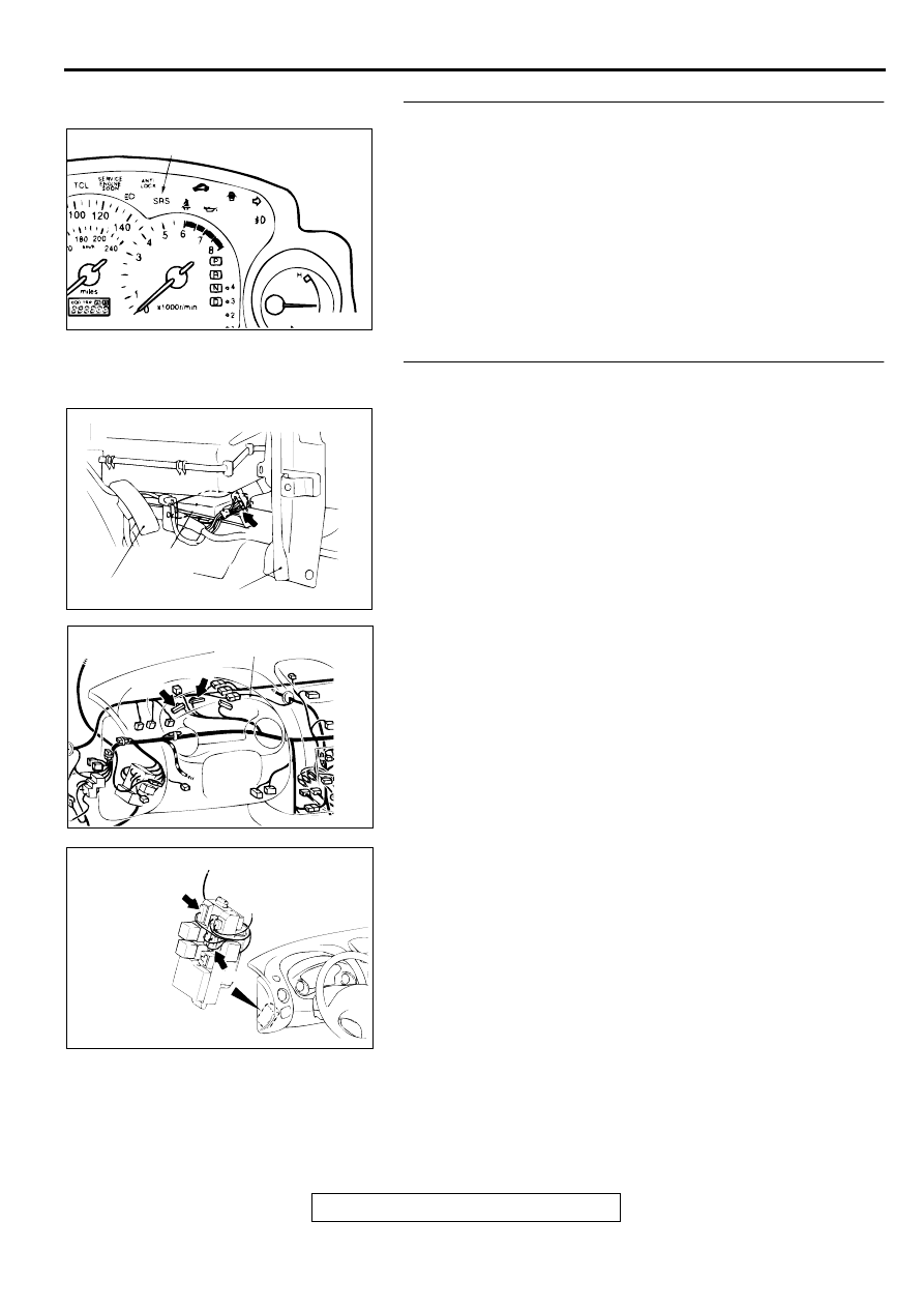
STEP 2. Check the SRS warning light bulb.
Q: Has the SRS warning light bulb blown?

YES : Replace the SRS warning light bulb. Then go to Step 

6.

NO :  Go to Step 3.

STEP 3. Check the harness wires between the ignition 
switch (IG1) and SRS-ECU connector C-72.
NOTE: After inspecting intermediate connectors C-41, C-42, C-
101, C-104 inspect the wiring harness. If intermediate 
connectors C-41, C-42, C-101, C-104 are damaged, repair or 
replace them. Refer to GROUP 00E, Harness Connector 
Inspection 

P.00E-2

. Then go to Step 6.

Q: Are the harness wires between the ignition switch (IG1) 

and SRS-ECU connector C-72 in good condition?
YES : 
Go to Step 4.
NO :  Repair them. Then go to Step 6.

AC000346AB

SRS WARNING LIGHT

AC000358AD

SRS-ECU

ACCELERATOR PEDAL

CENTER REINFORCEMENT(LH)

CONNECTOR: C-72

AC000370AC

CONNECTOR: C-41, C-42

C-42

C-41

COMBINATION METER

AC000371AC

CONNECTORS: C-101, C-104

C-301

C-308

JUNCTION
BLOCK
(FRONT VIEW)

SRS AIR BAG DIAGNOSIS

TSB Revision

SUPPLEMENTAL RESTRAINT SYSTEM (SRS)

52B-36

STEP 4. Check the ground line at the SRS-ECU connector 
C-72 by backprobing.
(1) Do disconnect the connector C-72.
(2) Measure the resistance between terminal 3 and ground by 

backprobing.

Should be less than 2 ohm.

Q: Is the resistance between terminal 3 and ground less 

than 2 ohm?
YES : 
Go to Step 6.
NO :  Go to Step 5.

STEP 5. Check the harness wires between SRS-ECU 
connector C-72 and ground.
Q: Are the harness wires between SRS-ECU connector C-

72 and ground in good condition?
YES : 
Go to Step 6.
NO :  Repair them. Then go to Step 6.

STEP 6. Check for DTC.

Q: Is any of DTC 43 or 44 output?

YES : There is no action to be taken.
NO :  This diagnosis is compleate.(If no malfunctions are 

not found in all steps, an intermittent malfunction is 
suspected. Refer to GROUP 00, How to Use 
Troubleshooting/Inspection Service Points 

 How to 

Cope with Intermittent Malfunction 

P.00-6

.) 

AC000368AC

C-72 CONNECTOR HARNESS SIDE VIEW

AC000358AD

SRS-ECU

ACCELERATOR PEDAL

CENTER REINFORCEMENT(LH)

CONNECTOR: C-72

SRS AIR BAG DIAGNOSIS

TSB Revision

SUPPLEMENTAL RESTRAINT SYSTEM (SRS)

52B-37

DTC 71: Right side-air bag module (squib) system fault 1
DTC 72: Right side-air bag module (squib) system fault 2
DTC 75: Right side-air bag module (squib) system fault power supply circuit
DTC 76: Right side-air bag module (squib) system fault ground circuit

CIRCUIT OPERATION

The SRS-ECU judges how severe a collision is 
by detecting signals from the left and right side 
impact sensors and the analog G-sensor. If the 
impact is over a predetermined level, the SRS-
ECU outputs an ignition signal. At this time, if the 
safing G-sensor is on, the SRS air bag will inflate.

The ignition signal is input to the air bag module 
to inflate the air bag.

DTC SET CONDITIONS

These DTC are output if there is abnormal 
resistance between the input terminals of the side 
air bag module (RH) (squib). The most likely 
causes for this code to be set are shown in the 
table below:

TROUBLESHOOTING HINTS

Damaged wiring harnesses or connectors

Malfunction of the side air bag module (RH) 
(squib)

Malfunction of the SRS-ECU

AC003885AB

Side Air Bag Module (RH) (Squib) Circuit

AC000358AF

CONNECTOR: C-74

SRS-ECU

ACCELERATOR PEDAL

CENTER REINFORCEMENT (LH)

AC002976AB

CONNECTOR: D-19

SRS AIR BAG DIAGNOSIS

TSB Revision

SUPPLEMENTAL RESTRAINT SYSTEM (SRS)

52B-38

DIAGNOSIS

Required Special Tools:

MB991502: Scan Tool (MUT-II)

MB991613: SRS Check Harness

STEP 1. Check the side air bag module line using the scan 
tool and MB991613 SRS Check harness.
(1) Disconnect side air bag module (RH) connector D-19.
(2) Connect special tool MB991613 connector (1).
(3) Connect the negative battery terminal.
(4) Erase the DTC memory. 

Q: Is DTC 71, 72, 75 or 76 output?

YES : Go to Step 2.
NO :  Replace the seat back assembly of the front seat 

(RH). Refer to GROUP 52A, Front Seat 

P.52A-18

Then go to Step 3.

STEP 2. Check the harness wires between SRS-ECU 
connector C-74 and side air bag module (RH) connector D-
19
Q: Are the harness wires between SRS-ECU connector C-

74 and side air bag module (RH) connector D-19 in good 
condition?
YES : 
Go to Step 3.
NO :  Repair them. Then go to Step 3.

DTC

SYMPTOMS

71

Short circuit in side air bag module (RH) (squib) or harness

72

Open circuit in side air bag module (RH) (squib) or harness

Malfunction of connector contact

75

Short circuit in side air bag module (RH) (squib) harness leading to the power supply

76

Short circuit in side air bag module (RH) (squib) harness leading to the ground

AC002977AB

MB991613

1

D-19

AC000358AF

CONNECTOR: C-74

SRS-ECU

ACCELERATOR PEDAL

CENTER REINFORCEMENT (LH)

AC002976AB

CONNECTOR: D-19


Content   ..  675  676  677  678   ..