Mitsubishi Eclipse / Eclipse Spyder (2000-2002). Service and repair manual - part 610
POWER STEERING GEAR BOX ASSEMBLY
TSB Revision
POWER STEERING
37A-35
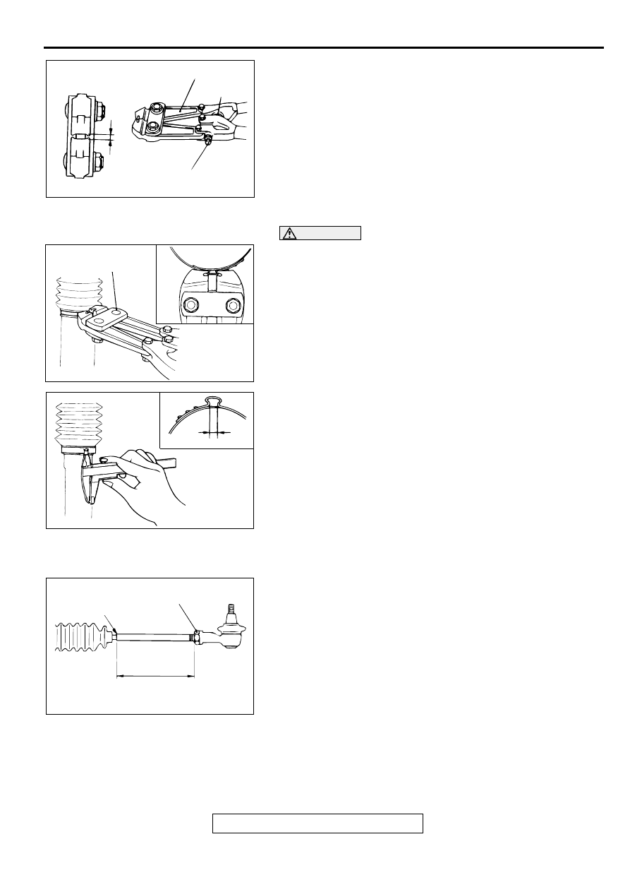
>>N<< BELLOWS BAND INSTALLATION
1. Turn the adjusting bolt of special tool MB991561 to adjust
the opening dimension (W) to the standard value.
NOTE: The dimension (W) is adjusted by approximately 0.7
mm (0.03 inch) per one turn.
NOTE: Do not turn the adjusting bolt more than one turn.
Standard value (W): 1.9 mm (0.07 inch)
<When more than 1.9 mm (0.07 inch)>: Screw in the
adjusting bolt.
<When less than 1.9 mm (0.07 inch)>: Loosen the
adjusting bolt.
CAUTION
•
Hold the rack housing, and use special tool MB991561
to crimp the bellows band securely.
•
Crimp the bellows band until special tool MB991561
touches the stopper.
2. Use special tool MB991561 to crimp the bellows band.
3. Check that crimped width (A) is within the standard value.
Standard value (A): 1.4
−
1.8 mm (0.06
−
0.07 inch)
<When more than 1.8 mm (0.07 inch)>: Readjust the
dimension (W) of step (1) to the value calculated by
the following equation, and repeat step (2).
W = 5.5 mm (0.22 inch)
−
A [Example: if (A) is 1.9 mm
(0.07 inch), (W) is 3.6 mm (0.14 inch).]
<When less than 1.4 mm (0.06 inch)>: Remove the
bellows band, readjust the dimension (W) of step (1) to
the value calculated by the following equation, and
use a new bellows band to repeat steps (2) to (3).
W = 5.5 mm (0.22 inch)
−
A [Example: if (A) is 1.3 mm
(0.05 inch), (W) is 4.2 mm (0.17 inch).]
>>O<< TIE ROD END/TIE ROD END JAM NUT
INSTALLATION
Screw in the tie rod end to achieve the right and left length as
illustrated. Lock with the jam nut.
ACX01164 AB
W
MB991561
ADJUSTING BOLT
STOPPER
ACX01165 AB
MB991561
ACX01166 AB
A
AC001011AC
JAM NUT
EDGE OF BELLOWS
ASSEMBLY GROOVE
2.4L ENGINE: 192 mm (7.6 in)
3.0L ENGINE <ECLIPSE>: 200 mm (7.9 in)
3.0L ENGINE <ECLIPSE SPYDER>: 197 mm (7.8 in)