Mitsubishi Eclipse / Eclipse Spyder (2000-2002). Service and repair manual - part 584
 

  Index      Mitsubishi     Mitsubishi Eclipse / Eclipse Spyder (2000-2002). Service and repair manual


Search            


Content   ..  582  583  584  585   ..


Mitsubishi Eclipse / Eclipse Spyder (2000-2002). Service and repair manual - part 584


ANTI-SKID BRAKING SYSTEM (ABS) DIAGNOSIS

TSB Revision

ANTI-LOCK BRAKING SYSTEM (ABS)

35B-27

SYMPTOM PROCEDURES

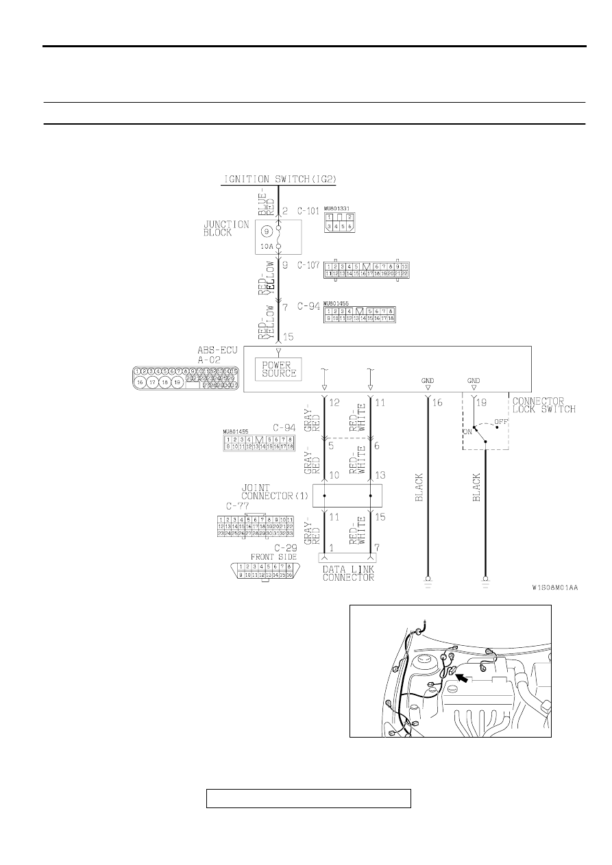
INSPECTION PROCEDURE 1: Communication between the Scan Tool and ABS-ECU Is not Possible. 

NOTE: CONNECTOR LOCK SWITCH
ON: The ABS-ECU connector A-02 is connected.
OFF: The ABS-ECU connector A-02 is disconnected.

Data Link Connector Circuit

AC001985

CONNECTOR: A-02

AD

ANTI-SKID BRAKING SYSTEM (ABS) DIAGNOSIS

TSB Revision

ANTI-LOCK BRAKING SYSTEM (ABS)

35B-28

CIRCUIT OPERATION

The diagnostic output is made from the ABS-
ECU (terminal 11) to the diagnostic output 
terminal (terminal 7) of the data link connector.

When the data link connector's diagnostic test 
mode control terminal (terminal 1) is grounded, 
the ABS-ECU (terminal 12) will go into diagnostic 
mode.

TECHNICAL DESCRIPTION (COMMENT)
When communication with the scan tool is not 
possible, the cause is probably an open circuit in the 
ABS-ECU power circuit or an open circuit in the 
diagnostic output circuit.

TROUBLESHOOTING HINTS (The most likely 
causes for this case:)

Blown fuse

Damaged wiring harness or connector

Malfunction of the hydraulic unit (Integrated with 
ABS-ECU)

DIAGNOSIS

Required Special Tool:

MB991223: Harness Set

AC004429AB

CONNECTOR: C-29

COMBINATION METER

AC004427AB

CONNECTOR: C-77

COMBINATION 
METER

AC004410AB

CONNECTOR: C-94

AC004413AB

CONNECTORS: C-101, C-107

C-107

C-101

ANTI-SKID BRAKING SYSTEM (ABS) DIAGNOSIS

TSB Revision

ANTI-LOCK BRAKING SYSTEM (ABS)

35B-29

STEP 1. Check the power supply circuit at the ABS-ECU 
connector A-02.
(1)Disconnect the ABS-ECU connector A-02 and measure at 

the harness side.

(2)Start the engine.
(3)Measure the voltage between terminal 15 and ground.

Q: Is the voltage approximately 12 volts (battery positive 

voltage)? 
YES : 
Go to Step 3.
NO :  Go to Step 2.

STEP 2. Check the harness wire between the ignition 
switch (IG2) and the ABS-ECU connector A-02.
NOTE: After inspecting the intermediate connector C-94, C-
101, or C-107, inspect the wire. If the intermediate connector 
C-94, C-101, or C-107 is damaged, repair or replace it. Refer to 
GROUP 00E, Harness Connector Inspection 

P.00E-2

If the 

connector has been repaired or replaced, go to Step 3 .

Q: Is the harness wire between the ignition switch (IG2) 

and the ABS-ECU connector A-02 damaged?
YES : 
Repair it and go to Step 5.
NO :  Go to Step 3.

AC000947

A-02 (HARNESS SIDE)

AB

AC001985

CONNECTOR: A-02

AD

AC004410AB

CONNECTOR: C-94

AC004413AB

CONNECTORS: C-101, C-107

C-107

C-101

ANTI-SKID BRAKING SYSTEM (ABS) DIAGNOSIS

TSB Revision

ANTI-LOCK BRAKING SYSTEM (ABS)

35B-30

STEP 3. Check the harness wires between the ABS-ECU 
connector A-02 and the data link connector C-29.
NOTE: After inspecting the intermediate connector C-77 or C-
94, inspect the wires. If the intermediate connector C-77 or C-
94 is damaged, repair or replace it. Refer to GROUP 00E, 
Harness Connector Inspection 

P.00E-2

If the connector has 

been repaired or replaced, go to Step 4.

Q: Is any of the harness wires between the ABS-ECU 

connector A-02 and the data link connector C-29 
damaged?
YES : 
Repair it and go to Step 5.
NO :  Go to Step 4.

AC001985

CONNECTOR: A-02

AD

AC004429AB

CONNECTOR: C-29

COMBINATION METER

AC004427AB

CONNECTOR: C-77

COMBINATION 
METER

AC004410AB

CONNECTOR: C-94


Content   ..  582  583  584  585   ..