Mitsubishi Eclipse / Eclipse Spyder (2000-2002). Service and repair manual - part 554
 

  Index      Mitsubishi     Mitsubishi Eclipse / Eclipse Spyder (2000-2002). Service and repair manual


Search            


Content   ..  552  553  554  555   ..


Mitsubishi Eclipse / Eclipse Spyder (2000-2002). Service and repair manual - part 554


STRUT ASSEMBLY

TSB Revision

FRONT SUSPENSION

33A-9

BALL JOINT DUST COVER CHECK

M1332008600064

1. Press the dust cover with your finger to check that there are 

no cracks or damage in the dust cover.

2. If the dust cover is cracked or damaged, replace the lower 

arm assembly or stabilizer link.

NOTE: If the dust cover is cracked or damaged, it is possible 
that there may also be damage to the ball joint.

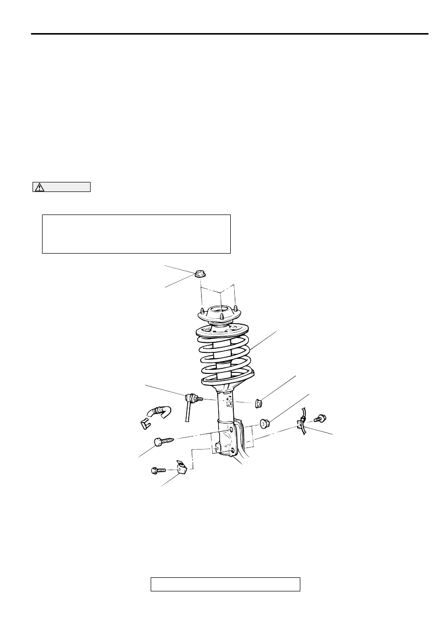
STR U T A SSEM BLY

REMOVAL AND INSTALLATION

M1332001100057

CAUTION

For vehicles with ABS, be careful when handling the pole piece at the tip of the speed sensor so as 
not to damage it by striking against other parts.

Post-installation Operation

Check the Dust Cover for Cracks or Damage by Pushing 
it with Your Finger.

Front Wheel Alignment Adjustment (Refer to 

P.33A-6

.)

AC001083AB

44 ± 5 N·m
33 ± 3 ft-lb

300 ± 24 N·m
221 ± 18 ft-lb

44 ± 10 N·m
33 ± 7 ft-lb

5

6

2

3

4

1

REMOVAL STEPS

STRUT TOWER BAR <ECLIPSE 
SPYDER> (REFER TO GROUP 
42, STRUT TOWER BAR 

P.42-11

.)

1.

BRAKE HOSE CLAMP

2.

FRONT SPEED SENSOR 
HARNESS CLAMP <VEHICLES 
WITH ABS>

3.

STABILIZER LINK

<<A>>

4.

BOLTS

5.

NUT

6.

STRUT ASSEMBLY

REMOVAL STEPS (Continued)

STRUT ASSEMBLY

TSB Revision

FRONT SUSPENSION

33A-10

REMOVAL SERVICE POINT

<<A>> BOLTS REMOVAL
1. Suspend the lower arm from the vehicle with wire.

2. Remove the strut and knuckle connection.

INSPECTION

M1332001200065

Check for oil leaks from the strut assembly.

Check the strut assembly for damage or deformation.

DISASSEMBLY AND ASSEMBLY

M1332001300051

Required Special Tools:

MB991176: Special Spanner

MB991237: Spring Compressor

MB991238: Arm Set

AC001084

8

9

10

N

2

1

3

4

5

6

7

64 ± 5 N·m
47 ± 4 ft-lb

AD

DISASSEMBLY STEPS

1.

DUST COVER

<<A>> >>A<<

2

.

JAM NUT

3.

STRUT INSULATOR

4.

SPRING SEAT, UPPER

5.

SPRING PAD, UPPER

6.

BUMP RUBBER

7.

DUST COVER

8.

COIL SPRING

9.

SPRING PAD, LOWER

<<B>>

10. STRUT ASSEMBLY

DISASSEMBLY STEPS (Continued)

STRUT ASSEMBLY

TSB Revision

FRONT SUSPENSION

33A-11

DISASSEMBLY SERVICE POINTS

<<A>> JAM NUT REMOVAL

CAUTION

To hold the coil spring securely, install special tools 
MB991237 and MB991238 evenly as shown (parallel 
with each other).

Do not use an impact wrench to tighten the bolt of 
special tool MB991237, otherwise the special tool will 
break.

1. Use special tools MB991237 and MB991238 to compress 

the coil spring.

WARNING

Do not use an impact wrench to remove the jam nut. 
Vibration of the impact wrench will cause special 
tools MB991237 and MB991238 to slip and cause 
bodily harm.

2. Use special tool MB991176 to secure the strut, and then 

remove the jam nut.

<<B>> STRUT ASSEMBLY REMOVAL

WARNING

Wear goggles when drilling to protect your eyes from 
flying metal debris.

The gas must be discharged from the strut assembly before 
discarding it. Place the assembly horizontally with its piston rod 
extended. Then drill a hole of approximately 3 mm (0.1 inch) in 
diameter at the location shown in the illustration and discharge 
the gas.

AC001085 AB

MB991238

MB991237

AC001086

MB991237

MB991176

AB

AC001087

STRUT ASSEMBLY

TSB Revision

FRONT SUSPENSION

33A-12

ASSEMBLY SERVICE POINT

>>A<< JAM NUT INSTALLATION

CAUTION

Do not use an impact wrench to tighten the bolt of special 
tool MB991237, otherwise the special tool will break.
1. With the coil spring held compressed by special tools 

MB991237 and MB991238, temporarily tighten the jam nut.

2. Using a rod as shown, line up the holes in the strut assembly 

spring lower seat with the hole in the spring upper seat.

3. Align both ends of the coil spring with the grooves in spring 

seat, and then loosen special tools MB991237 and 
MB991238.

CAUTION

Do not use an impact wrench to tighten the jam nut, 
otherwise the jam nut will not be tightened securely.
4. Using special tool MB991176, tighten the jam nut to 64 

±

 5 

N

m (47 

±

 4 ft-lb).

INSPECTION

M1332001400047

Check the bearing for wear or rust.

Check the rubber parts for damage or deterioration.

Check the spring for deformation, deterioration or damage.

Check the shock absorber for deformation.

AC001085 AB

MB991238

MB991237

AC001088 AB

ROD

AC001089

MB991176

64 ± 5 N·m
47 ± 4 ft-lb

AD


Content   ..  552  553  554  555   ..