Mitsubishi Eclipse / Eclipse Spyder (2000-2002). Service and repair manual - part 530
 

  Index      Mitsubishi     Mitsubishi Eclipse / Eclipse Spyder (2000-2002). Service and repair manual


Search            


Content   ..  528  529  530  531   ..


Mitsubishi Eclipse / Eclipse Spyder (2000-2002). Service and repair manual - part 530


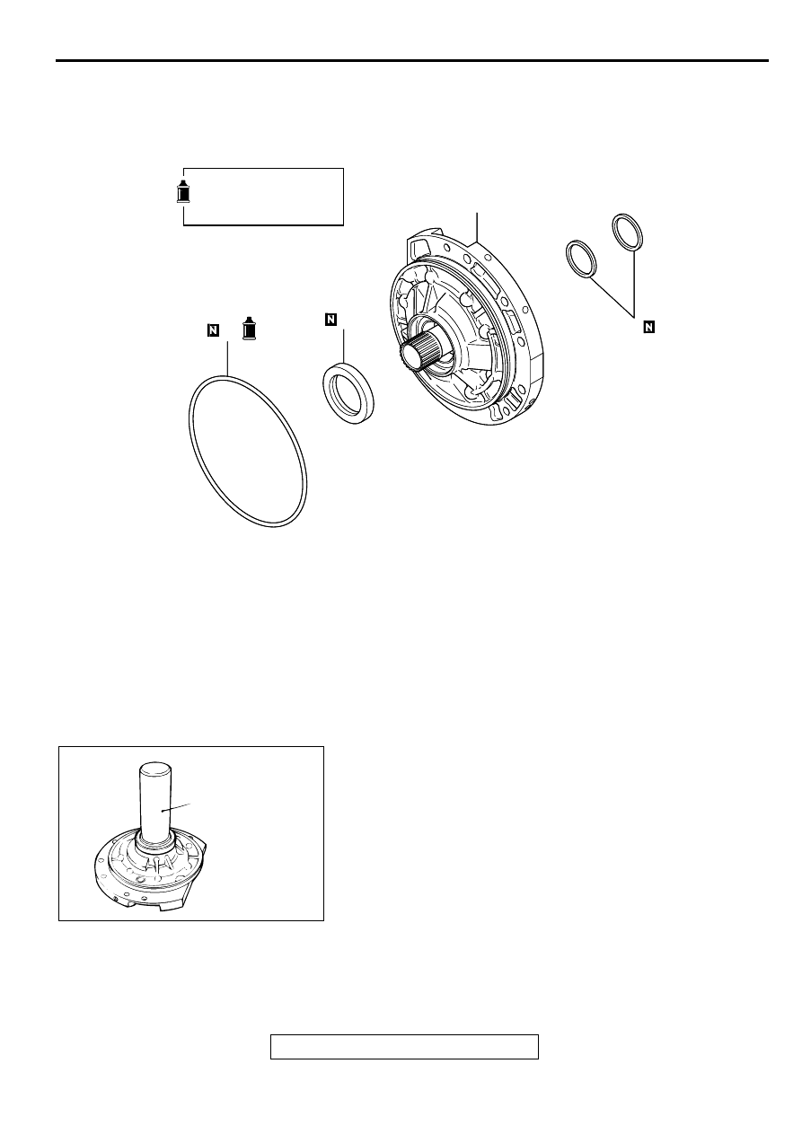
OIL PUMP

TSB Revision

AUTOMATIC TRANSAXLE OVERHAUL

23B-51

O IL PU M P

DISASSEMBLY AND ASSEMBLY

M1233001300024

Required Special Tool:
MD998334: Oil Seal Installer

ASSEMBLY SERVICE POINTS

>>A<< OIL SEAL INSTALLATION
1. Apply a small amount of ATF to the lip of oil seal.

2. Use special tool MD998334 to tap the oil seal in the oil pump 

body.

>>B<< O-RING INSTALLATION
Install a new O-ring to the outer groove of the oil pump, and 
apply ATF or petroleum jelly (Vaseline) to the O-ring.

AKX01125

AKX01125

APPLY AUTOMATIC 
TRANSMISSION FLUID 
TO ALL MOVING PARTS 
BEFORE INSTALLATION.

3

4

2

1

AB

DISASSEMBLY STEPS

>>B<<

1.

O-RING

2.

SEAL RING

>>A<<

3.

OIL SEAL

4.

OIL PUMP ASSEMBLY

DISASSEMBLY STEPS (Continued)

AKX01041

MD998334

AB

UNDERDRIVE CLUTCH AND INPUT SHAFT

TSB Revision

AUTOMATIC TRANSAXLE OVERHAUL

23B-52

UN D ERD RIVE CLU TCH  A N D  IN PU T SHA FT

DISASSEMBLY AND ASSEMBLY

M1233024500029

Required Special Tools:
MB991628: Spring Compressor <F4A42>
MB991629: Spring Compressor <F4A51>

MD998907: Spring Compressor
MD998924: Spring Compressor Retainer

AKX01126

AKX01126

13

10

15

15

10

12

13

11

14

11

12

14

6

8

9

8

3

2

2

3

1

1

9

5

4

4

5

7

6

7

APPLY AUTOMATIC 
TRANSMISSION FLUID 
TO ALL MOVING PARTS 
BEFORE INSTALLATION.

AB

DISASSEMBLY STEPS
1. SNAP RING
2. INPUT SHAFT
3. SEAL RING

>>D<<

4. SNAP RING

>>C<<

5. CLUTCH REACTION PLATE

>>C<<

6. CLUTCH DISC

<<A>> >>C<<

7. CLUTCH PLATE

>>B<<

8. SNAP RING

9. SPRING RETAINER

>>A<<

10. D-RING
11. RETURN SPRING
12. UNDERDRIVE CLUTCH PISTON

>>A<<

13. D-RING

>>A<<

14. D-RING
15. UNDERDRIVE CLUTCH RETAINER

DISASSEMBLY STEPS (Continued)

UNDERDRIVE CLUTCH AND INPUT SHAFT

TSB Revision

AUTOMATIC TRANSAXLE OVERHAUL

23B-53

DISASSEMBLY SERVICE POINT

<< A>> SNAP RING REMOVAL
1. Set special tools MD998907 and MD998924 as shown in the 

illustration.

2. Compress the return spring and remove the snap ring.

ASSEMBLY SERVICE POINTS

>>A<< D-RING INSTALLATION
1. Install a D-ring in the groove in the underdrive clutch retainer 

and piston, and in the groove in the outside of the spring 
retainer. Be careful not to twist or damage the D-rings.

2. Apply ATF or petroleum jelly (Vaseline) to the D-rings.

>>B<< SNAP RING INSTALLATION
1. Place the snap ring on top of the spring retainer, and then 

set special tool MD998907 as shown in the illustration.

2. Compress the return spring and install the snap ring.

AKX01042

MD998924

MD998907

AB

AKX01042

MD998924

MD998907

AB

REVERSE AND OVERDRIVE CLUTCH

TSB Revision

AUTOMATIC TRANSAXLE OVERHAUL

23B-54

>>C<< CLUTCH PLATE/CLUTCH DISC/CLUTCH REACTION 
PLATE INSTALLATION

CAUTION

Immerse the clutch disc in ATF before assembling it. 
Especially if the clutch disc is new, use it only after it has 
been immersed in ATF for at least two hours.
1. Assemble the four clutch plates and four clutch discs one on 

top of the other inside the underdrive clutch retainer. All four 
clutch plates should be assembled so that the places with no 
teeth (marked "A") are aligned with the holes in the retainer 
(marked "B").

2. Install the clutch reaction plate in the direction shown.

In the same way as the clutch plates, assemble them so that 
the areas with no teeth (marked "A") are aligned with the 
holes in the retainer (marked "B").

>>D<< SNAP RING INSTALLATION
1. Install the snap ring into the groove of clutch retainer.

2. Set special tools MB991628 <F4A42>, MB991629 <F4A51> 

and MD998924 as shown in the illustration, and then 
compress the clutch element.

3. Check that the clearance between the snap ring and the 

clutch reaction plate is within the standard value. If not within 
the standard value, select a snap ring to adjust.

Standard value: 1.6 

 1.8 mm (0.0630 

 0.0709 inch)

REVER SE A ND  O VERD R IVE CLUTC H

DISASSEMBLY AND ASSEMBLY

M1233024800020

NUMBER OF CLUTCH DISCS AND PLATES

AKX01044

B

A

AB

AKX01105

CLUTCH PLATES

ROUNDED EDGE

PISTON 
SIDE

CLUTCH DISCS

AB

CLUTCH 
REACTION 
PLATE

AKX01045

MB991628 
<F4A42>
OR
MB991629 
<F4A51>

MD998924

AB

MODEL

PRESSURE 
PLATE

CLUTCH DISC

CLUTCH PLATE

CLUTCH 
REACTION 
PLATE

Over drive clutch

F4A42

-

4

4

1

F4A51

1

4

3

1

Reverse clutch

-

2

2

1


Content   ..  528  529  530  531   ..