Mitsubishi Eclipse / Eclipse Spyder (2000-2002). Service and repair manual - part 490
 

  Index      Mitsubishi     Mitsubishi Eclipse / Eclipse Spyder (2000-2002). Service and repair manual


Search            


Content   ..  488  489  490  491   ..


Mitsubishi Eclipse / Eclipse Spyder (2000-2002). Service and repair manual - part 490


AUTOMATIC TRANSAXLE DIAGNOSIS

TSB Revision

AUTOMATIC TRANSAXLE

23A-252

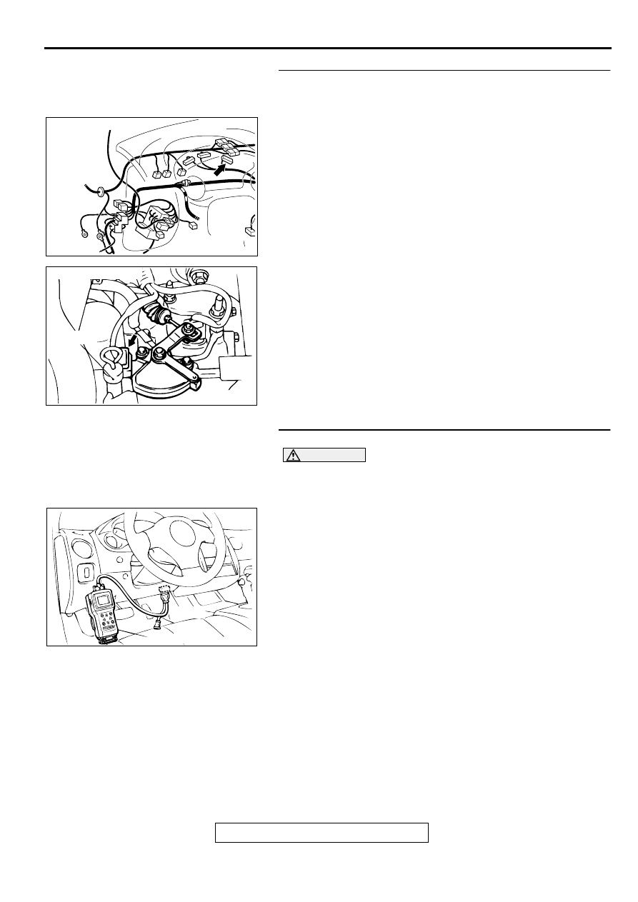
STEP 10. Check harness for short circuit to ground 
between combination meter connector C-43 terminal 9 and 
Park/Neutral position switch connector B-41 terminal 4.
Q: Is the harness wire in good condition?

YES : Go to Step 11.
NO :  Repair it.

STEP 11. Using scan tool MB991502, check the light bulb.

CAUTION

To prevent damage to scan tool MB991502, always turn the 
ignition switch to "LOCK" (OFF) position before 
connecting or disconnecting scan tool MB991502.
(1) Connect scan tool MB991502 to the data link connector.
(2) Turn the ignition switch to "ON" position.

The "N" range light in the combination meter flushes.

(3) Turn the ignition switch to "LOCK" (OFF) position.

Q: Does the "N" range light flush?

YES : This malfunction is intermittent. Refer to GROUP 00, 

How to Use Troubleshooting/Inspection Service 
Points 

 How to Cope with Intermittent Malfunction 

P.00-6

.

NO :  Replace the PCM.

AC001729 AO

CONNECTOR: C-43

AC001844

CONNECTOR: B-41

DIPSTICK

AB

AC001252

MB991502

16 PIN

AB

AUTOMATIC TRANSAXLE DIAGNOSIS

TSB Revision

AUTOMATIC TRANSAXLE

23A-253

SYMPTOM PROCEDURES

INSPECTION PROCEDURE 1: Vehicle does not Move

COMMENT
If the engine does not start when the selector lever is 
in "P" or "N" position, the cause is probably a 
malfunction of Park/Neutral position switch system, 
transaxle control cable assembly, engine system, 
torque converter or oil pump.

TROUBLESHOOTING HINTS (The most likely 

causes for this case:)

Malfunction of the Park/Neutral position switch

Malfunction of the transaxle control cable 
assembly

Malfunction of the engine system

Malfunction of the torque converter

Malfunction of the oil pump

Malfunction of the PCM

DIAGNOSIS

REQUIRED SPECIAL TOOL:
MB991502: Scan Tool (MUT-II)

STEP 1. Using scan tool MB991502, read the A/T 
diagnostic trouble code.

CAUTION

To prevent damage to scan tool MB991502, always turn the 
ignition switch to "LOCK" (OFF) position before 
connecting or disconnecting scan tool MB991502.
(1) Connect scan tool MB991502 to the data link connector.
(2) Turn the ignition switch to "ON" position.
(3) Read the A/T diagnostic trouble code.
(4) Turn the ignition switch to "LOCK" (OFF) position.

Q: Is A/T diagnostic trouble code numbers "27" or "28" 

displayed?
YES : 
Refer to 

P.23A-135

P.23A-163

code number 27, 28: 

Park/Neutral Position Switch System.

NO :  Go to Step 2.

STEP 2. Check the transaxle control cable assembly.
Move the selector lever to each position, and check if the 
manual control lever position of the Park/Neutral position 
switch corresponds to the selector lever position.

Q: Is the manual control lever position correct?

YES : Go to Step 3.
NO :  Repair the transaxle control cable. Refer to 

P.23A-

340

Park/Neutral Position Switch and Control Cable 

Adjustment. Confirm that the malfunction symptom is 
correct.

AC001252

MB991502

16 PIN

AB

AC001856

P

R

N

D

3

2

L

PARK/NEUTRAL
POSITION SWITCH

MANUAL
CONTROL
LEVER

AB

AUTOMATIC TRANSAXLE DIAGNOSIS

TSB Revision

AUTOMATIC TRANSAXLE

23A-254

STEP 3. Check the engine.
Refer to GROUP 13A <2.4L Engine>, Diagnosis 

 Trouble 

Symptom Chart 

 Starting 

P.13A-22

 or GROUP 13B <3.0L 

Engine>, Diagnosis 

 Trouble Symptom Chart 

 Starting 

P.13B-21

.

Q: Is the inspection result good?

YES : Go to Step 4.
NO :  Repair or replace the appropriate engine 

components.

STEP 4. Check the torque converter.
(1) Remove the transaxle.
(2) Check the torque converter for installation condition 

(whether installed in a slanted direction or not), its spline or 
its teeth for damage. Refer to GROUP 23B, Transaxle 

P.22B-8

.

Q: Is the torque converter in good condition?

YES : Go to Step 5.
NO :  Repair or replace it.

STEP 5. Replace the oil pump.
Replace the oil pump (Oil pump cannot be repaired). Refer to 
GROUP 23B, Transaxle 

P.22B-8

Confirm that the malfunction 

symptom is eliminated.

Q: Is the symptom eliminated?

YES : Diagnosis is complete.
NO :  Go to Step 6.

STEP 6. Replace the PCM.

Q: Is the symptom eliminated?

YES : Diagnosis is complete.
NO :  Start over at Step 1.

INSPECTION PROCEDURE 2: Does not Move Forward

COMMENT
If the vehicle does not move forward when the 
selector lever is shifted from "N" to "D," "2" or "L" 
range while the engine is idling, the cause is 
probably abnormal line pressure or a malfunction of 
the underdrive clutch or valve body.

TROUBLESHOOTING HINTS (The most likely 

causes for this case:)

Abnormal line pressure

Malfunction of the underdrive solenoid valve

Malfunction of the underdrive clutch

Malfunction of the valve body

Malfunction of the PCM

AC001857

AC001858

AUTOMATIC TRANSAXLE DIAGNOSIS

TSB Revision

AUTOMATIC TRANSAXLE

23A-255

DIAGNOSIS

REQUIRED SPECIAL TOOL:
MB991502: Scan Tool (MUT-II)

STEP 1. Using scan tool MB991502, check actuator test 
item 02: Underdrive Solenoid Valve.

CAUTION

To prevent damage to scan tool MB991502, always turn the 
ignition switch to "LOCK" (OFF) position before 
connecting or disconnecting scan tool MB991502. 
(1) Connect scan tool MB991502 to the data link connector.
(2) Turn the ignition switch to "ON" position.
(3) Set scan tool MB991502 to actuator test mode for item 02: 

Underdrive Solenoid Valve.

An operation sound should be heard from solenoid 
valve when solenoid valve is operated.

(4) Turn the ignition switch to "LOCK" (OFF) position.

Q: Is the solenoid valve operating properly?

YES : Go to Step 2.
NO :  Repair or replace the underdrive solenoid valve. 

Refer to GROUP 23B, Valve Body 

P.23B-69

Then 

confirm that the symptom is eliminated.

STEP 2. Check the hydraulic pressure.
Measure the hydraulic pressure of each element when the 
selector lever is at the "L" range, and check if each hydraulic 
pressure is within the standard value. Refer to 

P.23A-30

Hydraulic Pressure Test.

Q: Is the hydraulic pressure within the standard value?

YES : Go to Step 3.
NO :  Go to Step 4.

STEP 3. Check the underdrive clutch system.
(1) Remove the valve body cover and valve body. Refer to 

P.23A-353

, Transaxle Assembly and GROUP 23B, 

Transaxle 

P.23B-11

.

(2) Blow compressed air into the underdrive clutch oil orifice of 

the transaxle case, and check if the underdrive clutch piston 
moves and air pressure is maintained in that condition.

Q: Is the air pressure maintained?

YES : Go to Step 4.
NO :  Go to Step 5.

AC001252

MB991502

16 PIN

AB

AC001859

UNDERDRIVE
CLUTCH OIL
ORIFICE

AB


Content   ..  488  489  490  491   ..