Mitsubishi Eclipse / Eclipse Spyder (2000-2002). Service and repair manual - part 407
 

  Index      Mitsubishi     Mitsubishi Eclipse / Eclipse Spyder (2000-2002). Service and repair manual


Search            


Content   ..  405  406  407  408   ..


Mitsubishi Eclipse / Eclipse Spyder (2000-2002). Service and repair manual - part 407


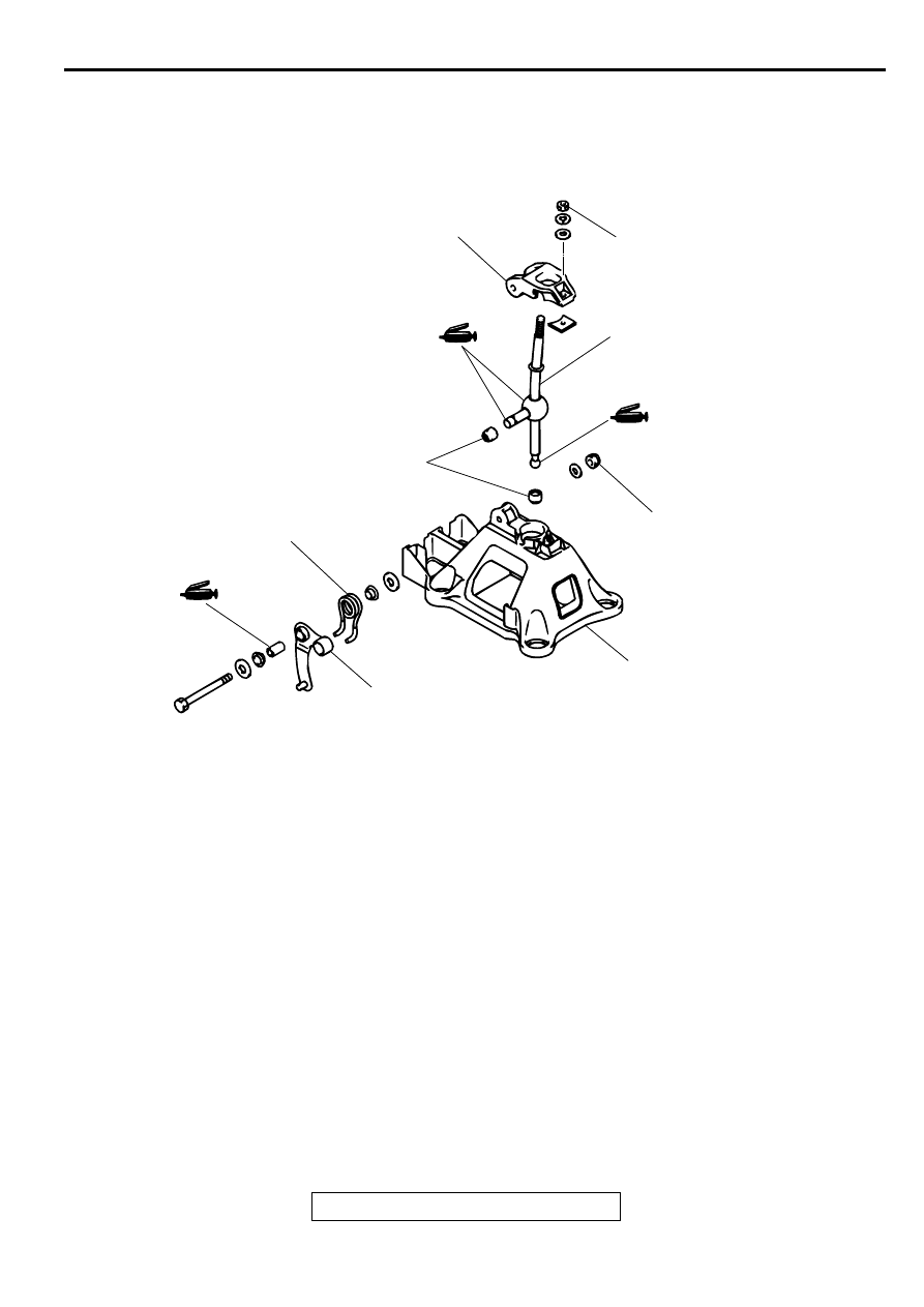
SHIFT LEVER ASSEMBLY

TSB Revision

MANUAL TRANSAXLE

22A-13

SH IFT LEVER  A SSEM BLY

DISASSEMBLY AND ASSEMBLY

M1221004000069

AC001626

1

2

3

4

5

6

5.0 ± 1.0 N·m
44 ± 9 in-lb

6.0 ± 2.0 N·m
53 ± 18 in-lb

AB

DISASSEMBLY STEPS

1.

SELECT LEVER

2.

RETURN SPRING

3.

RETAINER

4.

SHIFT LEVER

5.

SHIFT LEVER BUSHING

6.

LEVER BASE

DISASSEMBLY STEPS 

TRANSAXLE ASSEMBLY

TSB Revision

MANUAL TRANSAXLE

22A-14

TR A N SAXLE A SSEM B LY

REMOVAL AND INSTALLATION <2.4L ENGINE>

M1221002700103

CAUTION

*: Indicates parts which should be temporarily tightened, and then fully tightened after placing the 
vehicle fully on the ground and loading the full weight of the engine on the vehicle body.

Pre-removal Operation

Transaxle Oil Draining (Refer to 

P.22A-9

.)

Battery and Battery Tray Removal (Refer to GROUP 54A, 
Battery 

P.54A-8

.)

Air Cleaner Assembly Removal (Refer to GROUP 15, Air 
Cleaner 

P.15-5

.)

Post-installation Operation

Air Cleaner Assembly Installation (Refer to GROUP 15, 
Air Cleaner 

P.15-5

.)

Battery and Battery Tray Installation (Refer to GROUP 
54A, Battery 

P.54A-8

.)

Transaxle Oil Refilling (Refer to 

P.22A-9

.)

Check the Dust Cover for Cracks or Damage by Pushing 
it with Finger

Shift Lever Operation Check

Speedometer Operation Check

Wheel Alignment Adjustment (Refer to GROUP 33, On-
vehicle Service 

 Wheel Alignment Check and 

Adjustment 

P.33A-6

.)

AC001755

81 ± 12 N·m*
60 ± 9 ft-lb*

57 ± 7 N·m
42 ± 5 ft-lb

48 ± 5 N·m
36 ± 3 ft-lb

13 ± 2 ft-lb

48 ± 5 N·m
36 ± 4 ft-lb

30 ± 3 N·m
23 ± 2 ft-lb

108 ± 10 N·m
80 ± 7 ft-lb

44 ± 10 N·m
33 ± 7 ft-lb

45 ± 10 N·m*
34 ± 7 ft-lb*

29 ± 4 N·m
21 ± 4 ft-lb

8.8 ± 1.0 N·m
78 ± 9 in-lb

48 ± 6 N·m
36 ± 4 ft-lb

26 ± 4 N·m
19 ± 3 ft-lb

45 ± 5 N·m
34 ± 3 ft-lb

45 ± 5 N·m*
34 ± 3 ft-lb*

93 ± 15 N·m
69 ± 11 ft-lb

74 ± 4 N·m
55 ± 3 ft-lb

10

9

10

5

1

3

2

4

13

19

17

11

12

16

18

8

15

14

7

N

N

N

AB

TRANSAXLE ASSEMBLY

TSB Revision

MANUAL TRANSAXLE

22A-15

Required Special Tools:

MB991113: Steering Linkage Puller

MB991453: Engine Hanger Assembly

MZ203827: Engine Lifter

REMOVAL STEPS

1.

SHIFT CABLE AND SELECT 
CABLE CONNECTION (REFER 
TO 

P.22A-10

.)

2.

BACKUP LIGHT SWITCH 
CONNECTOR

3.

VEHICLE SPEED SENSOR 
CONNECTOR

<<A>>

4.

STARTER MOTOR

<<B>>

5.

CLUTCH RELEASE CYLINDER 
CONNECTION

6.

TRANSAXLE ASSEMBLY UPPER 
PART COUPLING BOLTS

<<C>>

7.

CENTERMEMBER ASSEMBLY

8.

REAR ROLL STOPPER

<<D>>

9.

TRANSAXLE MOUNT BRACKET

>>C<<

10. TRANSAXLE MOUNT STOPPER
11. STABILIZER LINK CONNECTION 

<STRUT SIDE>

12. WHEEL SPEED SENSOR CABLE 

CONNECTION <VEHICLES 
WITH ABS>

13. BRAKE HOSE CLAMP

<<E>>

14. TIE ROD END CONNECTION

<<E>>

15. LOWER ARM CONNECTION

<<G>>

16. DRIVESHAFT CONNECTION
17. BELL HOUSING COVER
18. TRANSAXLE ASSEMBLY 

LOWER PART COUPLING 
BOLTS

<<H>>

19. TRANSAXLE ASSEMBLY

REMOVAL STEPS (Continued)

TRANSAXLE ASSEMBLY

TSB Revision

MANUAL TRANSAXLE

22A-16

<3.0L ENGINE>

CAUTION

*: Indicates parts which should be temporarily tightened, and then fully tightened after placing the 
vehicle fully on the ground and loading the full weight of the engine on the vehicle body.

Pre-removal Operation

Transaxle Oil Draining (Refer to 

P.22A-9

.)

Battery and Battery Tray Removal (Refer to GROUP 54A, 
Battery 

P.54A-8

.)

Air Cleaner Assembly Removal (Refer to GROUP 15, Air 
Cleaner 

P.15-5

.)

Front Exhaust Pipe Removal (Refer to GROUP 15, 
Exhaust Pipe 

P.15-19

.)

Post-installation Operation

Air Cleaner Assembly Installation (Refer to GROUP 15, 
Air Cleaner 

P.15-5

.)

Battery and Battery Tray Installation (Refer to GROUP 
54A, Battery 

P.54A-8

.)

Transaxle Oil Refilling (Refer to 

P.22A-9

.)

Check the Dust Cover for Cracks or Damage by Pushing 
it with Finger

Shift Lever Operation Check

Speedometer Operation Check

Wheel Alignment Adjustment (Refer to GROUP 33A, On-
vehicle Service 

 Wheel Alignment Check and Adjust-

ment 

P.33A-6

.)

Front Exhaust Pipe Installation (Refer to GROUP 15, 
Exhaust Pipe 

P.15-21

.)

AC001756

74 ± 4 N·m
55 ± 3 ft-lb

93 ± 15 N·m
69 ± 11 ft-lb

108 ± 10 N·m
80 ± 7 ft-lb

29 ± 4 N·m
21 ± 3 ft-lb

45 ± 5 N·m
34 ± 3 ft-lb

45 ± 5 N·m
34 ± 3 ft-lb

45 ± 5 N·m*
34 ± 3 ft-lb*

35 ± 6 N·m
26 ± 4 ft-lb

40 ± 5 N·m
30 ± 3 ft-lb

88 ± 10 N·m
65 ± 7 ft-lb

44 ± 10 N·m
33 ± 7 ft-lb

45 ± 10 N·m*
34 ± 7 ft-lb*

30 ± 3 N·m
23 ± 2 ft-lb

74 ± 9 N·m
54 ± 7 ft-lb

18 ± 3 N·m
13 ± 2 ft-lb

74 ± 9 N·m
54 ± 7 ft-lb

81 ± 12 N·m*
60 ± 9 ft-lb*

57 ± 7 N·m
42 ± 5 ft-lb

10

9

10

5

6

2

3

1

6

4

20

13

11

12

16

15

14

7

8

17

18

19

N

N

AB


Content   ..  405  406  407  408   ..