Mitsubishi Eclipse / Eclipse Spyder (2000-2002). Service and repair manual - part 306
 

  Index      Mitsubishi     Mitsubishi Eclipse / Eclipse Spyder (2000-2002). Service and repair manual


Search            


Content   ..  304  305  306  307   ..


Mitsubishi Eclipse / Eclipse Spyder (2000-2002). Service and repair manual - part 306


MULTIPORT FUEL INJECTION (MFI) DIAGNOSIS

TSB Revision

MULTIPORT FUEL INJECTION (MFI) <3.0L ENGINE>

13B-423

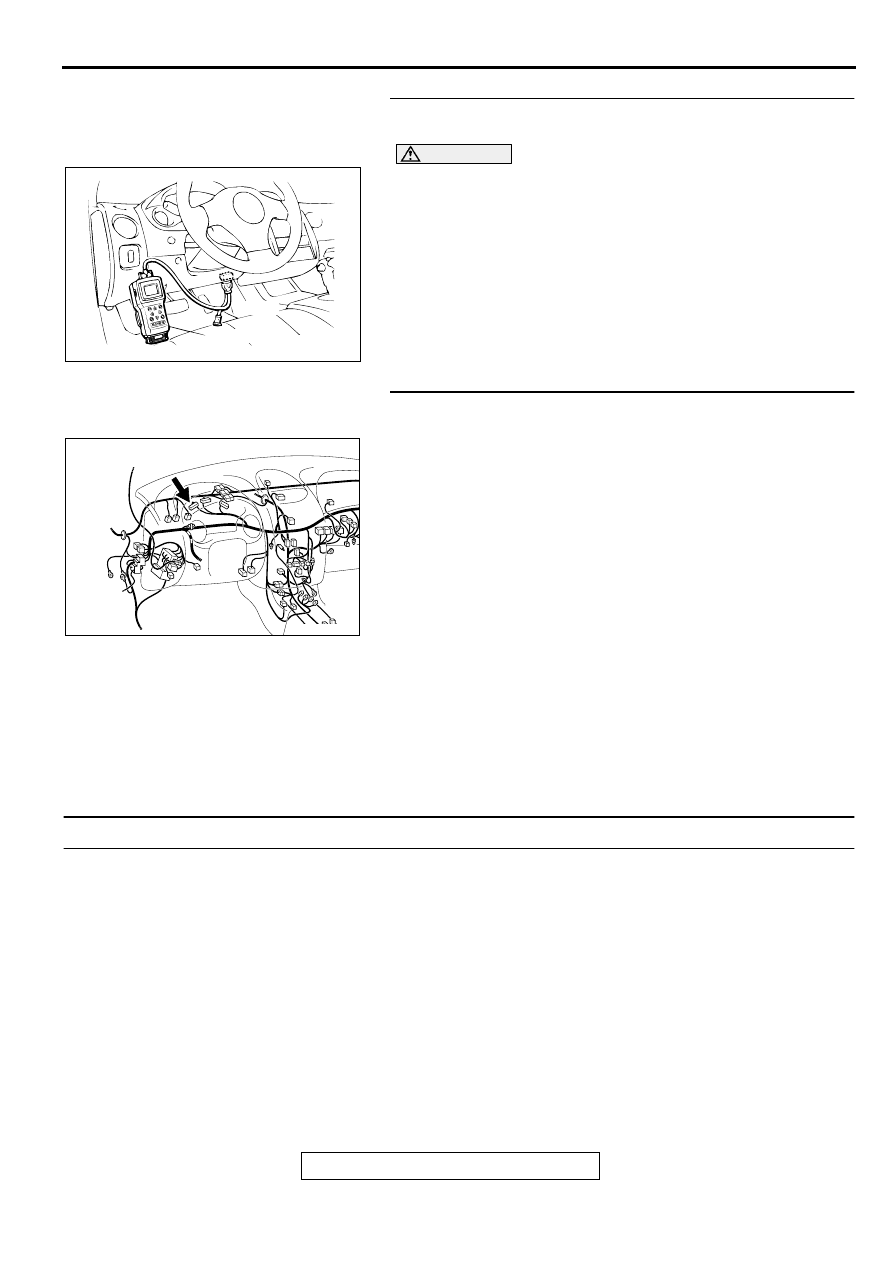
STEP 1. Using scan tool MB991502, read the diagnostic 
trouble code (DTC).

CAUTION

To prevent damage to scan tool MB991502, always turn the 
ignition switch to the "LOCK" (OFF) position before 
connecting or disconnecting scan tool MB991502.
(1) Connect scan tool MB991502 to the data link connector.
(2) Turn the ignition switch to the "ON" position.
(3) Read the DTC.
(4)  Turn the ignition switch to the "LOCK" (OFF) position.

Q: Is the DTC is output?

YES : Refer to Diagnostic Trouble Code Chart (

P.13B-18

). 

NO :  Go to Step. 2.

STEP 2. Check the continuity at combination meter 
harness side connector C-41.
(1) Disconnect the connector C-41 and measure at the harness 

side.

(2) Check for the continuity between terminal 41 and ground.

Should be open loop.

Q: Is the continuity normal?

YES : Replace the ECM or PCM. Then confirm that the 

malfunction symptom is eliminated.

NO :  Check harness connectors C-28 at the intermediate 

connector for damage, and repair or replace as 
required. Refer to GROUP 00E, Harness Connector 
Inspection (

P.00E-2

). If intermediate connectors is in 

good condition, repair harness wire between 
combination meter connector C-41 terminal 41 and 
ECM connector C-51 terminal 22 <M/T> or PCM 
connector C-52 terminal 22 <A/T> because of short 
circuit to ground. Then confirm that the malfunction 
symptom is eliminated.

INSPECTION PROCEDURE 5: Cranks, Won't Start

Cranks, Won't Start Circuit

Refer to, Ignition circuit malfunction (

P.13B-510

).

CIRCUIT OPERATION

Refer to, Ignition circuit malfunction (

P.13B-510

).

COMMENT

In cases such as the above, the cause is 
probably no spark, fuel delivery, or fuel quality 
problems. In addition, foreign materials (water, 
kerosene, etc.) may be mixed with the fuel.

TROUBLESHOOTING HINTS (The most likely 
causes for this case:) 

Malfunction of the ignition system.

Malfunction of the fuel pump system.

Malfunction of the injector system.

Malfunction of the ECM <M/T> or PCM <A/T>. 

Contaminated fuel.

AKX01177

16 PIN

MB991502

AB

AK000312AI

CONNECTOR:C-41

MULTIPORT FUEL INJECTION (MFI) DIAGNOSIS

TSB Revision

MULTIPORT FUEL INJECTION (MFI) <3.0L ENGINE>

13B-424

DIAGNOSIS

Required Special Tools
MB991502: Scan Tool (MUT-II)

STEP 1. Check the Battery positive voltage.
(1) Measure the Battery positive voltage during cranking.

The voltage should be 8 volts or more.

Q: Is the voltage normal?

YES : Go to Step 2.
NO :  Check the battery. Refer to GROUP 54A, Battery -

Battery check (

P.54A-5

). Then confirm that the 

malfunction symptom is eliminated.

STEP 2. Check the timing belt for breaks.

Q: Is the timing belt good condition?

YES : Go to Step 3.
NO :  Replace timing belt. Then confirm that the malfunction 

symptom is eliminated.

STEP 3 Using scan tool MB991502, check data list.

CAUTION

To prevent damage to scan tool MB991502, always turn the 
ignition switch to the "LOCK" (OFF) position before 
connecting or disconnecting scan tool MB991502.
(1) Connect scan tool MB991502 to the data link connector.
(2) Turn the ignition switch to the "ON" position.
(3) Check the following items in the data List. Refer to Data List 

Reference Table (

P.13B-517

).

a. Item 16: Power Supply Voltage.
b. Item 22: Crankshaft Position Sensor.

c. Item 21: Engine Coolant Temperature Sensor.

(4) Turn the ignition switch to the "LOCK" (OFF) position.

Q: Are they operating properly?

YES : Go to Step 4.
NO :  Repair or replace. Then confirm that the malfunction 

symptom is eliminated.

STEP 4. Using scan tool MB991502, check actuator test.
(1) Turn the ignition switch to the "ON" position.
(2) Check the following items in the actuator test. Refer to 

Actuator Test Reference Table (

P.13B-529

).

a. Item 07: Fuel pump.

(3) Turn the ignition switch to the "LOCK" (OFF) position.

Q: Is the actuator operating properly?

YES : Go to Step 5.
NO :  Repair or replace. Then confirm that the malfunction 

symptom is eliminated.

AKX01177

16 PIN

MB991502

AB

AKX01177

16 PIN

MB991502

AB

MULTIPORT FUEL INJECTION (MFI) DIAGNOSIS

TSB Revision

MULTIPORT FUEL INJECTION (MFI) <3.0L ENGINE>

13B-425

STEP 5. Check the ignition system.
(1) Connect the tachometer to inspection connector A-16X 

terminal 3.

(2) Crank the engine.

The tachometer should indicate cranking speed.

(3) Turn the ignition switch to the "LOCK" (OFF) position.

Q: Is the cranking speed normal?

YES : Go to Step 6.
NO :  Refer to INSPECTION PROCEDURE 33 

 Ignition 

Circuit System (

P.13B-510

).

STEP 6. Check the ignition timing.
(1) Check the ignition timing at cranking.

Standard value: 5

° 

BTDC 

±

 3

°

Q: Is the ignition timing normal?

YES : Go to Step 7.
NO :  Check that the crankshaft position sensor and timing 

belt cover are in the correct position. Then confirm 
that the malfunction symptom is eliminated.

STEP 7. Check the left bank injector.
(1) Disconnect the left bank injector connector B-02, B-06, B-

25.

(2) Measure the resistance between each injector side 

connector terminal 1 and 2.

Standard value: 13 

 16 ohm [at 20

° 

C (68

°

 F)]

Q: Is the resistance standard value?

YES : Go to Step 8.
NO :  Replace the faulty injector. Then confirm that the 

malfunction symptom is eliminated.

ACX02446

INSPECTION
CONNECTOR

CONNECTOR:A-16X

AD

AK000213AB

CONNECTORS : B-02, B-06, B-25

B-02 B-06 B-25

AK000559

2

1

INJECTOR SIDE
CONNECTOR

AB

MULTIPORT FUEL INJECTION (MFI) DIAGNOSIS

TSB Revision

MULTIPORT FUEL INJECTION (MFI) <3.0L ENGINE>

13B-426

STEP 8. Check the right bank injector resistance at injector 
intermediate connector B-48.
(1) Disconnect the injector intermediate connector B-48.
(2) Measure the resistance between each male connector side 

terminal.

a. Measure the resistance between terminal 1 and 2 when 

measuring No.1 cylinder injector

b. Measure the resistance between terminal 1 and 3 when 

measuring No.3 cylinder injector

c. Measure the resistance between terminal 1 and 4 when 

measuring No.5 cylinder injector

Resistance should be between 13 and 16 ohm [at 20

°

 C 

(68

°

 F)].

Q: Is the resistance normal?

YES : Go to Step 11.
NO :  Go to Step 9.

STEP 9. Check the right bank injector.
(1) Remove the intake manifold.
(2) Disconnect the right bank injector connector, which 

deviates from the standard value at Step 8.

(3) Measure the resistance between injector side connector 

terminal 1 and 2.

Standard value: 13 

 16 ohm [at 20

° 

C (68

°

 F)]

Q: Is the resistance standard value?

YES : Go to Step 10.
NO :  Replace the injector. Then confirm that the 

malfunction symptom is eliminated.

AK000209AC

CONNECTOR:B-48

AK000447

1 2

3 4

INJECTOR
INTERMEDIATE
CONNECTOR

AB

AK000210AB

B-05 B-26

B-01

CONNECTORS : B-01, B-05, B-26

AK000559

2

1

INJECTOR SIDE
CONNECTOR

AB


Content   ..  304  305  306  307   ..