Mitsubishi Eclipse / Eclipse Spyder (2000-2002). Service and repair manual - part 300
 

  Index      Mitsubishi     Mitsubishi Eclipse / Eclipse Spyder (2000-2002). Service and repair manual


Search            


Content   ..  298  299  300  301   ..


Mitsubishi Eclipse / Eclipse Spyder (2000-2002). Service and repair manual - part 300


MULTIPORT FUEL INJECTION (MFI) DIAGNOSIS

TSB Revision

MULTIPORT FUEL INJECTION (MFI) <3.0L ENGINE>

13B-399

STEP 12. Test the OBD-II drive cycle.
(1) Carry out a test drive with the drive cycle pattern. Refer to, 

Procedure 6 

 Other Monitor (

P.13B-4

).

(2) Check the diagnostic trouble code (DTC).

Q: Is the DTC P1400 is output?

YES : Retry the troubleshooting.
NO :  The inspection is complete.

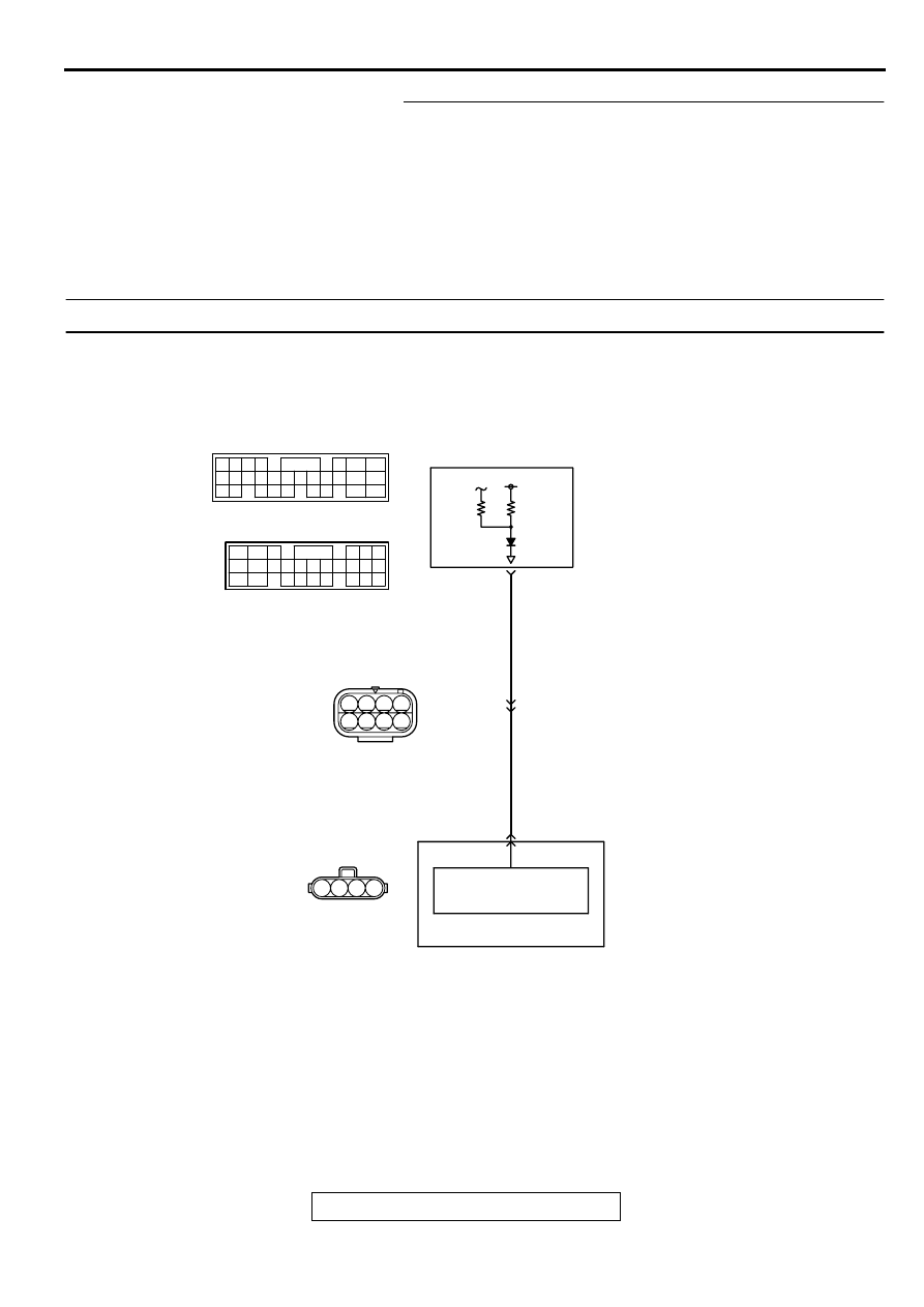
DTC P1500: Generator FR Terminal Circuit Malfunction

AK000710

4

3

2

6

3 4
7 8

1 2

5

1

YELL

OW

-BL

ACK

YELL

OW

-BL

ACK

ENGINE CONTROL
MODULE(ECM)<M/T>
OR
POWERTRAIN CONTROL
MODULE(PCM)<A/T>

GENERATOR

VOLTAGE
REGULATOR

      B-45
(MU802046)

     B-13
MU802749

52<M/T>
54<A/T>

3

4

65

43
50

42
49

41

48
60 61

64

46 47
58 59
67 68

45

56
66

52

51

44

53

62

54

63

57

55

 C-58<M/T>
(MU803782)

 C-55<A/T>
(MU803781)

42 43
48 49 50 51 52 53 54 55 56 57

46

45

44

58 59

60 61 62 63

64 65 66

47

41

MULTIPORT FUEL INJECTION (MFI) DIAGNOSIS

TSB Revision

MULTIPORT FUEL INJECTION (MFI) <3.0L ENGINE>

13B-400

CIRCUIT OPERATION

The ECM (terminal 52) <M/T> or PCM (terminal 
54) <A/T> apply a battery positive voltage into the 
generator FR terminal 4 via resistance inside the 
unit.

TECHNICAL DESCRIPTION

When the generator field coils are controlled, the 
generator FR terminal inputs signal to the ECM 
<M/T> or PCM <A/T>.

The ECM <M/T> or PCM <A/T> detects the 
generator output with the input signal, and 
controls the idle air control motor according to the 
generator output.

DTC SET CONDITIONS

Check Conditions

Engine speed is higher than 50 r/min.

Judgement Criteria

Input voltage from the generator FR terminal has 
continued to be not lower than 4.5V for 20 
seconds.

TROUBLESHOOTING HINTS (The most likely 
causes for this code to be set area:)

Open circuit in generator FR terminal circuit.

ECM failed. <M/T>

PCM failed. <A/T>

AK000735AB

CONNECTOR:B-45

AK000220

AK000220AB

CONNECTOR : B-13

AK000225

CONNECTOR : C-58<M/T>, C-55<A/T>

C-55

C-58

PCM<A/T>

ECM<M/T>

AI

MULTIPORT FUEL INJECTION (MFI) DIAGNOSIS

TSB Revision

MULTIPORT FUEL INJECTION (MFI) <3.0L ENGINE>

13B-401

DIAGNOSIS

STEP 1. Check the voltage at generator intermediate 
connector B-13 by backprobing
(1) Do not disconnect the connector B-13.
(2) Start the engine and run at idle.
(3) Measure the voltage between terminal 3 and ground by 

backprobing.

a. Engine: warming up
b. Radiator fan: stopped

c. Headlight switch: OFF to ON

d. Rear defogger switch: OFF to ON
e. Stoplight switch: OFF to ON

Voltage should be drops.

(4) Turn the ignition switch to the "LOCK" (OFF) position.

Q: Is the voltage normal?

YES : Go to Step 2.
NO :  Go to Step 4.

STEP 2. Check connector B-13 at generator intermediate 
connector for damage.
Q: Is the connector in good condition?

YES : Go to Step 3.
NO :  Repair or replace it. Refer to GROUP 00E, Harness 

Connector Inspection (

P.00E-2

). Then go to Step 11.

STEP 3. Check the trouble symptoms.
(1) Carry out a test drive with the drive cycle pattern. Refer to, 

Procedure 6 

 Other Monitor (

P.13B-4

).

(2) Check the diagnostic trouble code (DTC).

Q: Is the DTC P1500 is output?

YES : Replace the ECM or PCM. Then go to Step 11.
NO :  It can be assumed that this malfunction is intermittent. 

Refer to GROUP 00, How to Use Troubleshooting/
Inspection Service Points (

P.00-6

).

AK000262

B-13 CONNECTOR
HARNESS
SIDE VIEW

1 2 3 4
5 6 7 8

AB

AK000220

AK000220AB

CONNECTOR : B-13

MULTIPORT FUEL INJECTION (MFI) DIAGNOSIS

TSB Revision

MULTIPORT FUEL INJECTION (MFI) <3.0L ENGINE>

13B-402

STEP 4. Check connector B-13 at generator intermediate 
connector for damage.
Q: Is the connector in good condition?

YES : Go to Step 5.
NO :  Repair or replace it. Refer to GROUP 00E, Harness 

Connector Inspection (

P.00E-2

). Then go to Step 11.

STEP 5. Check connector B-45 at generator connector for 
damage.
Q: Is the connector in good condition?

YES : Go to Step 6.
NO :  Repair or replace it. Refer to GROUP 00E, Harness 

Connector Inspection (

P.00E-2

). Then go to Step 11.

STEP 6. Check the voltage at generator harness side 
connector B-45.
(1) Disconnect the connector B-45 and measure at the harness 

side.

(2) Turn the ignition switch to the "ON" position.
(3) Measure the voltage between terminal 4 and ground.

Voltage should be between 4.8 and 5.2 volts

(4) Turn the ignition switch to the "LOCK" (OFF) position.

Q: Is the voltage normal?

YES : Go to Step 9.
NO :  Go to Step 7.

AK000220

AK000220AB

CONNECTOR : B-13

AK000735AB

CONNECTOR:B-45

AK000263 AE

B-45 HARNESS
SIDE CONNECTOR

4 3 2 1


Content   ..  298  299  300  301   ..