Mitsubishi Eclipse / Eclipse Spyder (2000-2002). Service and repair manual - part 287
 

  Index      Mitsubishi     Mitsubishi Eclipse / Eclipse Spyder (2000-2002). Service and repair manual


Search            


Content   ..  285  286  287  288   ..


Mitsubishi Eclipse / Eclipse Spyder (2000-2002). Service and repair manual - part 287


MULTIPORT FUEL INJECTION (MFI) DIAGNOSIS

TSB Revision

MULTIPORT FUEL INJECTION (MFI) <3.0L ENGINE>

13B-347

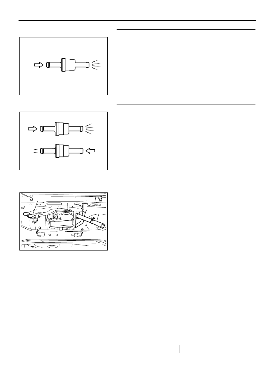
STEP 28. Check the check valve A.
(1) Only when you blow the check valve from the direction 

shown, it should pass air.

(2) When you blow the check valve, on air should leak from the 

check valve body.

Q: Is there any failure?

YES : Replace it, then perform the OBD-II drive cycle 

P.13B-4

.

NO :  Go to Step 29.

STEP 29. Check the check valve B.
(1) When you blow the check valve from the arrow direction 

shown above, it should pass more air.

(2) When you blow the check valve from the arrow direction 

shown below, it should pass less air.

(3) When you blow the check valve, on air should leak from the 

check valve body.

Q: Is there any failure?

YES : Replace it, then perform the OBD-II drive cycle 

P.13B-4

.

NO :  Go to Step 30.

STEP 30. Check for clogging in the evaporator line from 
hose J to hose K.
(1) The clogging test with a hand vacuum pump on each hose 

from hose J to hose K.

Q: Are there any clogs?

YES : Replace that hose, reinstall the filler neck assembly 

and filler neck protector, and perform the OBD-II drive 
cycle 

P.13B-4

.

NO :  Go to Step 31.

AC002076 AB

CHECK VALVE A

AC002078

CHECK VALVE B

AB

AC002033 AB

HOSE K

HOSE J

MULTIPORT FUEL INJECTION (MFI) DIAGNOSIS

TSB Revision

MULTIPORT FUEL INJECTION (MFI) <3.0L ENGINE>

13B-348

STEP 31. Check for clogging in the evaporator line from 
hose P.
(1) Remove the filler neck assembly. (Refer to GROUP 13C, 

Fuel Tank 

P.13C-6

.)

(2) Carry out the clogging test with a hand vacuum pump on 

each hose from hose P.

Q: Is there any clogs?

YES : Replace that hose, reinstall the fuel tank, and perform 

the OBD-II drive cycle 

P.13B-4

.

NO :  Reinstall the fuel tank. Then go to step 32.

STEP 32. Evaporative Emission System Monitor Test using 
scan tool MB991502.
(1) Turn the ignition switch to the "ON" position.
(2) Erase the DTCs using the scan tool MB991502.
(3) Check that the fuel cap is securely closed. (Tighten until 

three clicks are heard.)

(4) Start the engine.
(5) Select "System Test," and press the "YES" key.
(6) Select "Evap Leak Mon," and press the "YES" key.
(7) During the monitor, keep the accelerator pedal at the idling 

position.

NOTE: If the engine speed does not reach 2,000 r/min 
during the monitor test, adjustment of the Speed Adjusting 
Screw may be needed. Refer to 

P.13B-552

 and adjust to 

the standard value.

(8) Keep the engine speed and engine load within the specified 

range. When the monitor test starts, the "In Progress" item 
on the scan tool MB991502 will change from "NO" to "YES."

Q: What kind of message is displayed on scan tool 

MB991502?
When the message "Evap Leak Mon. Completed. Test 
Passed" is displayed : 
The evaporative emission system 

is working properly at this time. Explain to customer 
that improperly tightened fuel cap can cause MIL to 
turn on, and return the vehicle.

When the message "Evap Leak Mon. Completed. Test 
Failed and DTCs Set" is displayed : 
Go to Step 1.
When the message "Evap Lead Mon. discontinued. 
Retest again from the first" is displayed : 
Turn the 

ignition switch to the "LOCK" (OFF) position once, 
then repeat this monitor test from the start.

AC000195 AC

HOSE P

AC001252

MB991502

16 PIN

AB

MULTIPORT FUEL INJECTION (MFI) DIAGNOSIS

TSB Revision

MULTIPORT FUEL INJECTION (MFI) <3.0L ENGINE>

13B-349

DTC P0500: Vehicle Speed Sensor Malfunction <M/T>

AK000706

3

1

2 3

3

2

4 5 6

1 2 3
4 5 6

1

WHITE-

BLUE

WHITE-

BLUE

WHITE-

BLUE

BLA

CK

BLA

CK

BLA

CK-

WHITE

BLA

CK-

WHITE

BLA

CK-

WHITE

BLA

CK-

WHITE

GREEN

1

2

5V

     B-39
(MU802723)

VEHICLE SPEED
SENSOR

 B-36

ENGINE CONTROL
MODULE(ECM)

R

IG2

ST

LOCK

ACC

IG1

    C-101
MU801331

IGNITION
SWITCH

C-87

2

6

6

1

2

2

3

3

1

4

4

1

JOINT
CONNECTOR(2)

JUNCTION
BLOCK

80

12 13

15

17

16

14

19

18

8 9

7

20

2 3

1

6

4

5

11

10

   C-104
MU801457

16

15

18

17

14

20

22

21

9

7

1 2

5

19

3

33

32

30 31

29

28

25

24

23

27

26

6

11

13

4

10

8

12

C-78

7 8

5

3 4

35

34

10 11 12

2122 23 24

13 14 15

25 26 27

16

28

17

18 19 20

29

30 31

32 33

36 37

38

9

1 2

6

C-28

AUTO-CRUISE
 CONTROL SYSTEM
METER AND
 GAUGE
MULTI CENTER
 DISPLAY

80

87

81

94

85

82

84

93

86

98

99

74

92

73

83

88

91

95

97

96

100

89

78

71

90

76 77

75

72
79

      C-62
(MU803783)

MULTIPORT FUEL INJECTION (MFI) DIAGNOSIS

TSB Revision

MULTIPORT FUEL INJECTION (MFI) <3.0L ENGINE>

13B-350

CIRCUIT OPERATION

A 5-volt voltage is applied to the vehicle speed 
sensor output terminal (terminal 3) from the ECM 
(terminal 80). The vehicle speed sensor 
generates a pulse signal when the output 
terminal is opened and grounded.

TECHNICAL DESCRIPTION

The vehicle speed sensor converts the vehicle 
speed into pulse signals and inputs them to the 
ECM.

The vehicle speed sensor outputs a pulse signal 
while the vehicle is driven.

The ECM checks whether the pulse signal is 
output.

AK000218AC

CONNECTOR:B-39

AK000312AG

CONNECTOR:C-78

AK000219

CONNECTOR:C-87

AC

AK000733AC

CONNECTOR:C-28

AK000310

CONNECTOR:C-62

AC

AK000218AC

CONNECTOR:B-36

AK000311

AK000311

CONNECTOR:C-104

AC

AK000315

CONNECTOR:C-101

AC


Content   ..  285  286  287  288   ..