Mitsubishi Eclipse / Eclipse Spyder (2000-2002). Service and repair manual - part 214
 

  Index      Mitsubishi     Mitsubishi Eclipse / Eclipse Spyder (2000-2002). Service and repair manual


Search            


Content   ..  212  213  214  215   ..


Mitsubishi Eclipse / Eclipse Spyder (2000-2002). Service and repair manual - part 214


MULTIPORT FUEL INJECTION (MFI) DIAGNOSIS

TSB Revision

MULTIPORT FUEL INJECTION (MFI) <3.0L ENGINE>

13B-55

STEP 9. Check for open circuit between barometric 
pressure sensor connector B-14 terminal 5 and ECM 
connector C-58 terminal 49 <M/T> or PCM connector C-55 
terminal 57 <A/T>.
Q: Is the harness wire in good condition?

YES : Replace the ECM or PCM. Then go to Step 12.
NO :  Repair it. Then go to Step 12.

STEP 10. Check connector B-14 at barometric pressure 
sensor for damage.
Q: Is the connector in good condition?

YES : Go to Step 11.
NO :  Repair or replace it. Refer to GROUP 00E, Harness 

Connector Inspection (

P.00E-2

). Then go to Step 12.

STEP 11. Check connector C-58 at ECM <M/T> or 
connector C-55 at PCM <A/T> for damage.
Q: Is the connector in good condition?

YES : Replace the volume air flow sensor. Then go to Step 

12. 

NO :  Repair or replace it. Refer to GROUP 00E, Harness 

Connector Inspection (

P.00E-2

). Then go to Step 12.

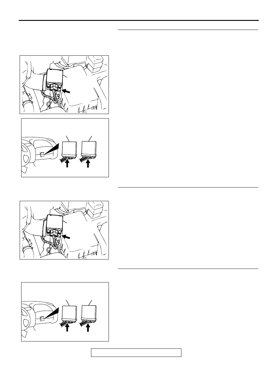
ACX02480

CONNECTOR : B-14

AF

BAROMETRIC
PRESSURE
SENSOR

AK000225

CONNECTOR : C-58<M/T>, C-55<A/T>

C-55

C-58

PCM<A/T>

ECM<M/T>

AI

ACX02480

CONNECTOR : B-14

AF

BAROMETRIC
PRESSURE
SENSOR

AK000225

CONNECTOR : C-58<M/T>, C-55<A/T>

C-55

C-58

PCM<A/T>

ECM<M/T>

AI

MULTIPORT FUEL INJECTION (MFI) DIAGNOSIS

TSB Revision

MULTIPORT FUEL INJECTION (MFI) <3.0L ENGINE>

13B-56

STEP 12. Test the OBD-II drive cycle.
(1) Carry out a test drive with the drive cycle pattern. Refer to 

P.13B-4

, Procedure 6 

 Other Monitor.

(2) Check the diagnostic trouble code (DTC).

Q: Is the DTC P0108 is output?

YES : Retry the troubleshooting.
NO :  The inspection is complete.

DTC P0111: Intake air temperature Circuit Range/Performance Problem

AK000687

2 3

7

4 5 6

1

BLA

CK

RED-BLUE

49<M/T>
57<A/T>

62<M/T>
64<A/T>

B-14

INTAKE AIR TEMPERATURE SENSOR
(INCORPORATED IN VOLUME AIR
FLOW SENSOR)

ENGINE CONTROL
MODULE(ECM)<M/T>
OR
POWERTRAIN CONTROL
MODULE(PCM)<A/T>

5

6

5V

65

43
50

42
49

41
48
60 61

64

46 47
58 59
67 68

45

56
66

52

51

44

53

62

54

63

57

55

 C-58<M/T>
(MU803782)

 C-55<A/T>
(MU803781)

42 43
48 49 50 51 52 53 54 55 56 57

46

45

44

58 59

60 61 62 63

64 65 66

47

41

MULTIPORT FUEL INJECTION (MFI) DIAGNOSIS

TSB Revision

MULTIPORT FUEL INJECTION (MFI) <3.0L ENGINE>

13B-57

CIRCUIT OPERATION

Approximately 5 volts are applied to the intake air 
temperature sensor output terminal (terminal 6) 
from the ECM (terminal 62) <M/T> or PCM 
(terminal 64) <A/T> via the resistor in the ECM 
<M/T> or PCM <A/T>. The ground terminal 
(terminal 5) is grounded with ECM (terminal 49) 
<M/T> or PCM (terminal 57) <A/T>.

The intake air temperature sensor is a negative 
temperature coefficient type of resistor. When the 
intake air temperature rises, the resistance 
decreases.

The intake air temperature sensor output voltage 
increases when the resistance increases and 
decreases when the resistance decreases.

TECHNICAL DESCRIPTION

The intake air temperature sensor converts the 
intake air temperature to a voltage.

The ECM <M/T> or PCM <A/T> checks whether 
this voltage is within a specified range.

DTC SET CONDITIONS

Check Conditions

Two seconds or more have passed since the 
engine was started.

Judgement Criteria

Intake air temperature sensor output voltage has 
continued to be 4.6 volts or higher [corresponding 
to an air intake temperature of -45

°

 C (-49

°

 F) or 

lower] for 2 seconds.

or

Intake air temperature sensor output voltage has 
continued to be 0.2 volt or lower [corresponding 
to an air intake temperature of 125

°

 C (257

°

 F) or 

higher] for 2 seconds.

TROUBLESHOOTING HINTS (The most likely 
causes for this code to be set are:)

Intake air temperature sensor failed.

Open or shorted intake air temperature sensor 
circuit, or loose connector.

ECM failed. <M/T>

PCM failed. <A/T>

DIAGNOSIS

Required Special Tools
MB991502: Scan Tool (MUT-II)

ACX02480

CONNECTOR : B-14

AG

INTAKE AIR
TEMPERATURE
SENSOR

AK000225

CONNECTOR : C-58<M/T>, C-55<A/T>

C-55

C-58

PCM<A/T>

ECM<M/T>

AI

MULTIPORT FUEL INJECTION (MFI) DIAGNOSIS

TSB Revision

MULTIPORT FUEL INJECTION (MFI) <3.0L ENGINE>

13B-58

STEP 1. Using scan tool MB991502, check data list item 13: 
Intake Air Temperature Sensor.

CAUTION

To prevent damage to scan tool MB991502, always turn the 
ignition switch to the "LOCK" (OFF) position before 
connecting or disconnecting scan tool MB991502.
(1) Connect scan tool MB991502 to the data link connector.
(2) Turn the ignition switch to the "ON" position.
(3) Set scan tool MB991502 to the data reading mode for item 

13, Intake Air Temperature Sensor.

The intake air temperature and temperature shown with 
the scan tool should approximately match.

(4) Turn the ignition switch to the "LOCK" (OFF) position.

Q: Is the sensor operating properly?

YES : It can be assumed that this malfunction is intermittent. 

Refer to GROUP 00, How to Use Troubleshooting/
Inspection Service Points (

P.00-6

).

NO :  Go to Step 2.

STEP 2. Check the sensor output voltage at intake air 
temperature sensor connector B-14 by backprobing.
(1) Do not disconnect the connector B-14.
(2) Turn the ignition switch to the "ON" position.
(3) Measure the voltage between terminal 6 and ground by 

backprobing.

When intake air temperature is 0

°

 C (32

°

 F), voltage 

should be 3.2 and 3.8 volts.

When intake air temperature is 20

°

 C (68

°

 F), voltage 

should be 2.3 and 2.9 volts.

When intake air temperature is 40

°

 C (104

°

 F), voltage 

should be 1.5 and 2.1 volts.

When intake air temperature is 80

°

 C (176

°

 F), voltage 

should be 0.4 and 1.0 volts.

(4) Turn the ignition switch to the "LOCK" (OFF) position.

Q: Is the voltage normal?

YES : Go to Step 3.
NO :  Go to Step 5.

STEP 3. Check connector B-14 at the intake air 
temperature sensor for damage.
Q: Is the connector in good condition?

YES : Go to Step 4.
NO :  Repair or replace it. Refer to GROUP 00E, Harness 

Connector Inspection (

P.00E-2

). Then go to Step 19.

AKX01177

16 PIN

MB991502

AB

AKX01524

B-14 CONNECTOR
HARNESS
SIDE VIEW

1 2 3 4 5 6 7

AC

ACX02480

CONNECTOR : B-14

AG

INTAKE AIR
TEMPERATURE
SENSOR


Content   ..  212  213  214  215   ..