Mitsubishi Eclipse / Eclipse Spyder (2000-2002). Service and repair manual - part 102
 

  Index      Mitsubishi     Mitsubishi Eclipse / Eclipse Spyder (2000-2002). Service and repair manual


Search            


Content   ..  100  101  102  103   ..


Mitsubishi Eclipse / Eclipse Spyder (2000-2002). Service and repair manual - part 102


MULTIPORT FUEL INJECTION (MFI) DIAGNOSIS

TSB Revision

MULTIPORT FUEL INJECTION (MFI) <2.4L ENGINE>

13A-107

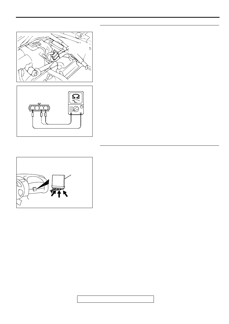
STEP 8. Check the throttle position sensor.
(1) Disconnect the connector B-07.
(2) Measure the resistance between throttle position sensor 

side connector terminal 1 and 4.

Standard value: 3.5 

 6.5 k

(3) Measure resistance between the throttle position sensor 

side connector terminal 1 and 3.

(4) Move the throttle valve from the idle position to the full-open 

position.

Resistance should change smoothly in proportion to the 
opening angle of the throttle valve.

Q: Is the resistance normal?

YES : Go to Step 9.
NO :  Replace the throttle position sensor.(Refer to 

P.13A-

489

Throttle Body.) Then go to Step 11

STEP 9. Check connector C-60 at ECM <M/T> or connector 
C-54, C-57 at PCM <A/T> for damage.
Q: Is the connector in good condition?

YES : Go to Step 10.
NO :  Repair or replace it. Refer to GROUP 00E, Harness 

Connector Inspection (

P.00E-2

). Then go to Step 11.

ACX02472

CONNECTOR : B-07

THROTTLE
POSITION
SENSOR

AE

AK000320

1 2 3 4

THROTTLE POSITION
SENSOR SIDE
CONNECTOR

AB

AK000280

C-54

C-60

ECM<M/T>
OR
PCM<A/T>

CONNECTORS:C-60<M/T>,C-54,C-57<A/T>

BD

C-57

MULTIPORT FUEL INJECTION (MFI) DIAGNOSIS

TSB Revision

MULTIPORT FUEL INJECTION (MFI) <2.4L ENGINE>

13A-108

STEP 10. Using scan tool MB991502, check data list item 
14: Throttle Position Sensor.

CAUTION

To prevent damage to scan tool MB991502, always turn the 
ignition switch to the "LOCK" (OFF) position before 
connecting or disconnecting scan tool MB991502.
(1) Connect scan tool MB991502 to the data link connector.
(2) Turn the ignition switch to the "ON" position.
(3) Set scan tool MB991502 to the data reading mode for item 

14, Throttle Position Sensor.

With the throttle valve in the idle position, voltage should 
be between 0.535 and 0.735 volts.

With the throttle valve in the full-open position, voltage 
should be between 4.5 and 5.5 volts.

(4) Turn the ignition switch to the "LOCK" (OFF) position.

Q: Is the sensor operating properly?

YES : It can be assumed that this malfunction is intermittent. 

Refer to GROUP 00, How to Use Troubleshooting/
Inspection Service Points (

P.00-6

).

NO :  Replace the ECM or PCM. Then go to Step 11.

STEP 11. Test the OBD-II drive cycle.
(1) Carry out a test drive with the drive cycle pattern. Refer to, 

Procedure 6 

 Other Monitor (

P.13A-5

).

(2) Check the diagnostic trouble code (DTC).

Q: Is the DTC P0123 is output?

YES : Retry the troubleshooting.
NO :  The inspection is complete.

DTC P0128: Coolant Thermostat Malfunction

TECHNICAL DESCRIPTION

The ECM <M/T> or PCM <A/T> checks the time 
for the engine coolant temperature to reach the 
judgment temperature.

DTC SET CONDITIONS

Check Conditions

Engine coolant temperature is between -10

° 

(14

° 

F) and 82

°

 C (180

° 

F) when the engine is 

started.

The engine coolant temperature 

 intake air 

temperature is 5

°

 C (48

° 

F) or less when the 

engine is started.

The intake air temperature when the engine is 
started 

 intake air temperature is 2

° 

C (36

° 

F) or 

less.

The volume air flow sensors output frequency is 
in the low frequency (50-100Hz or less) state for 
400 seconds or less.

Judgment Criteria

The time for the engine coolant temperature to 
rise to 82

°

 C (180

°

 F) takes longer than the 

specified time *.
*: Approximately 11 to 23 minutes when the 

engine coolant temperature at start is 20

°

 C 

(68

°

 F) or more.

Approximately 12 to 60 minutes when the engine 

coolant temperature at start is 20

° 

C (68

°

 F) 

or less.

Only one monitor during one drive cycle.

TROUBLESHOOTING HINTS (The most likely 
causes for this code to be set are:)

The thermostat is faulty

ECU failed. <M/T>

PCM failed. <A/T>

AKX01177

16 PIN

MB991502

AB

MULTIPORT FUEL INJECTION (MFI) DIAGNOSIS

TSB Revision

MULTIPORT FUEL INJECTION (MFI) <2.4L ENGINE>

13A-109

DIAGNOSIS

STEP 1. Check the cooling system.
Refer to GROUP 14, Engine Cooling Diagnosis 

P.14-2

.

Q: Is the cooling system normal?

YES : Replace the ECM or PCM. Then check that the DTC 

P0128 does not reset.

NO :  Repair it. Then check that the DTC P0128 does not 

reset.

DTC P0130: O

2

  Sensor Circuit Malfunction (sensor 1)

AK000657

4

1 2
3

BL

ACK

BL

ACK

WHITE

     B-17
MU802605

ENGINE CONTROL
MODULE(ECM)<M/T>
OR
POWERTRAIN CONTROL
MODULE(PCM)<A/T>

HEATED OXYGEN
SENSOR(FRONT)

FROM MFI RELAY

TO ECM
OR PCM

1

2

3

4

92<M/T>
57<A/T>*1

76<M/T>
71<A/T>*2

 C-60<M/T>
(MU803772)

 C-54<A/T>
(MU803781)

 C-57<A/T>
(MU803782)

NOTE
*1:PCM connector C-54<A/T>
*2:PCM connector C-57<A/T>

98

78

71

88 89

76 77

72
79
91

73
80

74

75

81
92

8283
93

8485

94

8687

9596

90

97

82

78

81

80

89 90 91 92

79

87

71

74

73

72

76

75

77

85

88

83 84

86

42 43
48 49 50 51 52 53 54 55 56 57

46

45

44

58 59

60 61 62 63

64 65 66

47

41

MULTIPORT FUEL INJECTION (MFI) DIAGNOSIS

TSB Revision

MULTIPORT FUEL INJECTION (MFI) <2.4L ENGINE>

13A-110

CIRCUIT OPERATION

A voltage corresponding to the oxygen 
concentration in the exhaust gas is sent to the 
ECM (terminal 76) <M/T> or PCM (terminal 71) 
<A/T> from the output terminal (terminal 4) of the 
heated oxygen sensor (front).

Terminal 2 of the heated oxygen sensor (front) is 
grounded with ECM (terminal 92) <M/T> or PCM 
(terminal 57) <A/T>.

TECHNICAL DESCRIPTION

The heated oxygen sensor (front) detects the 
concentration of oxygen in the exhaust gas; it 
converts those data to voltage, and inputs the 
resulting signals to the ECM <M/T> or PCM <A/
T>.

When the heated oxygen sensor (front) begins to 
deteriorate, the heated oxygen sensor signal 
response becomes poor.

The ECM <M/T> or PCM <A/T> forcibly varies 
the air/fuel mixture to make it leaner and richer, 
and checks the response speed of the heated 
oxygen sensor (front). In addition, the ECM <M/
T> or PCM <A/T> also checks for an open circuit 
in the heated oxygen sensor (front) output line.

DTC SET CONDITIONS

Check Conditions

Heated oxygen sensor (front) signal voltage has 
continued to be 0.2 volt or lower for three minutes 
or more after the starting sequence was 
completed.

Engine coolant temperature is higher than 82

°

 C 

(180

°

 F).

Engine speed is higher than 1,200 r/min.

Volumetric efficiency is higher than 25 percent.

Monitoring time: 7 seconds.

Judgment Criteria

Input voltage supplied to the ECM <M/T> or PCM 
<A/T> interface circuit is higher than 4.5 volts 
when 5 volts is applied to the heated oxygen 
sensor (front) output line via a resistor.

TROUBLESHOOTING HINTS (The most likely 
causes for this code to be set are:)

Heated oxygen sensor (front) deteriorated.

Open circuit in heated oxygen sensor (front) 
output line.

Open circuit in heated oxygen sensor (front) 
ground line.

ECM failed. <M/T>

PCM failed. <A/T>

DIAGNOSIS

Required Special Tools
MB991502: Scan Tool (MUT-II)
MD998464: Test Harness

ACX02476

CONNECTOR : B-17

HEATED OXYGEN
SENSOR (FRONT)

AD

AK000280

C-54

C-60

ECM<M/T>
OR
PCM<A/T>

CONNECTORS:C-60<M/T>,C-54,C-57<A/T>

BD

C-57


Content   ..  100  101  102  103   ..