Mitsubishi Eclipse / Eclipse Spyder (2000-2002). Service and repair manual - part 70
 

  Index      Mitsubishi     Mitsubishi Eclipse / Eclipse Spyder (2000-2002). Service and repair manual


Search            


Content   ..  68  69  70  71   ..


Mitsubishi Eclipse / Eclipse Spyder (2000-2002). Service and repair manual - part 70


PISTON AND CONNECTING ROD

TSB Revision

ENGINE OVERHAUL <3.0L ENGINE>

11D-51

>>E<< CONNECTING ROD CAP INSTALLATION
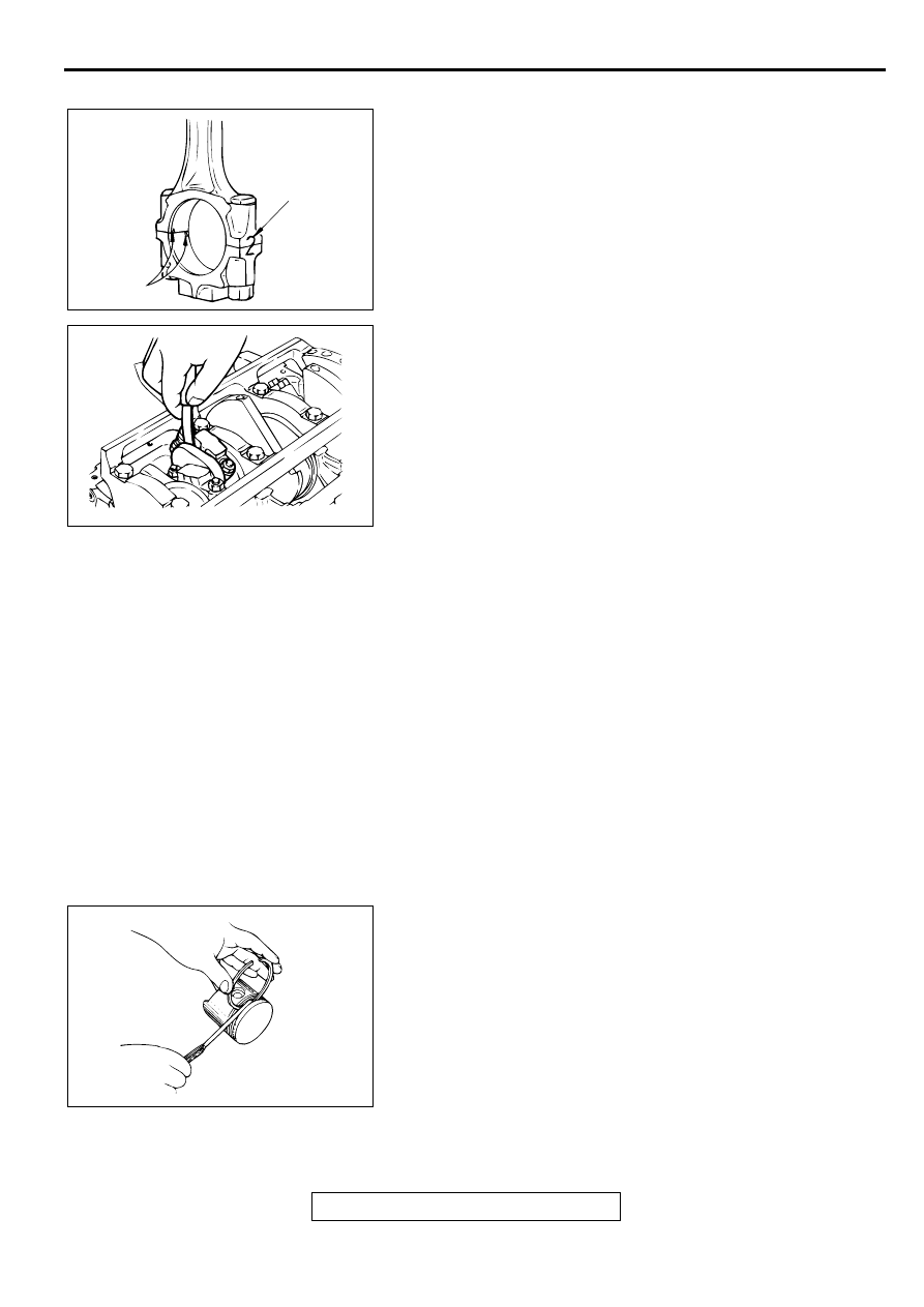
1. Mate the correct bearing cap with the correct connecting rod 

by checking with the alignment marks marked during 
disassembly. If a new connecting rod is used which has no 
alignment mark, position the notches for locking the bearing 
on the same side.

2. Check if the thrust clearance in the connecting rod big end is 

correct.

Standard value: 0.10 

 0.25 mm (0.004 

 0.009 inch)

Limit: 0.4 mm (0.02 inch)

INSPECTION

M1113008500042

PISTON
Replace the piston if scratches or seizure is evident on its 
surfaces (especially the thrust surface). Replace the piston if it 
is cracked.

PISTON PIN
1. Insert the piston pin into the piston pin hole with your thumb. 

You should feel a slight resistance. Replace the piston pin if 
it can be easily inserted or there is an excessive play.

2. The piston and piston pin must be replaced as an assembly.

PISTON RING 
1. Check the piston ring for damage, excessive wear, and 

breakage. Replace if defects are evident. If the piston has 
been replaced, the piston rings must also be replaced.

2. Check for clearance between the piston ring and ring 

groove. If it exceeds the limit, replace the ring or piston, or 
both.

Standard value: 

Number 1 0.03 

 0.07 mm (0.0012 

 0.0027 inch)

Number 2 0.02 

 0.06 mm (0.0008 

 0.0023 inch)

Limit: 0.1 mm (0.003 inch)

AKX00735

CYLINDER NO.

NOTCHES

AB

AKX00736

AKX00612

PISTON AND CONNECTING ROD

TSB Revision

ENGINE OVERHAUL <3.0L ENGINE>

11D-52

3. Insert the piston ring into the cylinder bore. Force the ring 

down with a piston, the piston crown being in contact with 
the ring, to correctly position it at right angles to the cylinder 
wall. Then, measure the end gap with a feeler gauge. 
If the ring gap is excessive, replace the piston ring.

Standard value: 

Number 1: 0.30 

 0.45 mm (0.012 

 0.017 inch)

Number 2: 0.45 

 0.60 mm (0.018 

 0.023 inch)

Oil: 0.20 

 0.60 mm (0.008 

 0.023 inch)

Limit:

Number 1, Number 2: 0.8 mm (0.03 inch)
Oil: 1.0 mm (0.03 inch)

CRANKSHAFT PIN OIL CLEARANCE (PLASTIC GAUGING 
MATERIAL METHOD)
1. Remove oil from the crankshaft pin and the connecting rod 

bearing.

2. Cut plastic gauging material to the same length as the width 

of the bearing and place it on the pin in parallel with its axis.

3. Install the connecting rod cap carefully and tighten the nuts 

to the specified torque.

4. Carefully remove the connecting rod cap.

5. Measure the width of the plastic gauging material at its 

widest part by using a scale printed on the plastic gauging 
material package.

Standard value: 0.02 

 0.05 mm (0.0008 

 0.0019 inch)

Limit: 0.1 mm (0.003 inch)

AKX00719

PUSH IN BY
PISTON

PISTON
RING
GAP

PISTON RING

AB

AKX00731AB

SCALE

AKX00609

CRANKSHAFT AND CYLINDER BLOCK

TSB Revision

ENGINE OVERHAUL <3.0L ENGINE>

11D-53

C R A N K SH A FT A N D  C YLIN D ER  B LO C K

REMOVAL AND INSTALLATION

M1113008700046

CAUTION

On the flexible flywheel equipped engines, do not remove any of the bolts "A" of the flywheel shown 
in the illustration. The balance of the flexible flywheel is adjusted in an assembled condition. 
Removing the bolt, therefore, can cause the flexible flywheel to be out of balance and result in 
damage.

AKX00683

11

APPLY ENGINE OIL TO ALL
MOVING PARTS BEFORE
INSTALLATION.

23 ± 2 N·m
17 ± 1 ft-lb

28 ± 2 N·m
21 ± 1 ft-lb

11 ± 1 N·m
95 ± 9 in-lb

74 ± 2 N·m
54 ± 1 ft-lb

11 ± 1 N·m
95 ± 9 in-lb

74 ± 2 N·m
54 ± 1 ft-lb

93 ± 5 N·m
69 ± 4 ft-lb

1

21

10

3

2

22

4

23

9

5

8

19

20

18

17

6

15

14

16

13

12

AB

7

REMOVAL STEPS
1. FLYWHEEL BOLT <M/T>
2. ADAPTER PLATE <M/T>
3 PLATE <M/T>
4. FLYWHEEL <M/T>
5. DRIVE PLATE BOLT <A/T>
6. ADAPTOR PLATE <A/T>
7. DRIVE PLATE <A/T>
8. REAR PLATE

>>F<<

9. OIL SEAL CASE ASSEMBLY

>>E<<

10.CRANKSHAFT REAR OIL SEAL
11. OIL SEAL CASE

>>D<<

12.BEARING CAP BOLT

>>D<<

13.BEARING CAP

>>C<<

14.THRUST BEARING A

>>C<<

15.THRUST BEARING B

>>B<<

16.CRANKSHAFT BEARING, LOWER
17.CRANKSHAFT

>>C<<

18.THRUST BEARING B

>>C<<

19.THRUST BEARING A

>>B<<

20.CRANKSHAFT BEARING, UPPER
21.KNOCK SENSOR

REMOVAL STEPS (Continued)

CRANKSHAFT AND CYLINDER BLOCK

TSB Revision

ENGINE OVERHAUL <3.0L ENGINE>

11D-54

Required Special Tool:
MD998718: Crankshaft Rear Oil Seal Installer

INSTALLATION SERVICE POINTS

>>A<< KNOCK SENSOR BRACKET INSTALLATION
Check that the bracket is in proper contact with the cylinder 
block boss and tighten to the specified torque in the order 
shown.

Tightening torque: 28 

±

 2 N

m (21 

±

 1 ft-lb)

>>B<< CRANKSHAFT BEARING INSTALLATION
When bearing replacement is required, select and install the 
correct bearing by the following procedure. 
1. Measure the crankshaft journal diameter and confirm its 

classification from the following table. In the case of a 
crankshaft supplied as a service part, identification colors/
marks of its journals are painted/stamped at the positions 
shown in the illustration.

>>A<<

22.KNOCK SENSOR BRACKET
23.CYLINDER BLOCK

REMOVAL STEPS (Continued)

AKX00649

TIMING BELT SIDE

AB

AKX00647

NO. 2
JOURNAL

LOCATION OF IDENTIFICATION COLOR

NO. 1
JOURNAL

NO. 3
JOURNAL

NO. 4
JOURNAL

AB


Content   ..  68  69  70  71   ..