Mitsubishi Eclipse. Technical Information Manual (1994) - part 91
 

  Index      Mitsubishi     Mitsubishi Eclipse. Technical Information Manual (1994)


Search            


Content   ..  89  90  91  92   ..


Mitsubishi Eclipse. Technical Information Manual (1994) - part 91


EQUIPMENT   ETACS

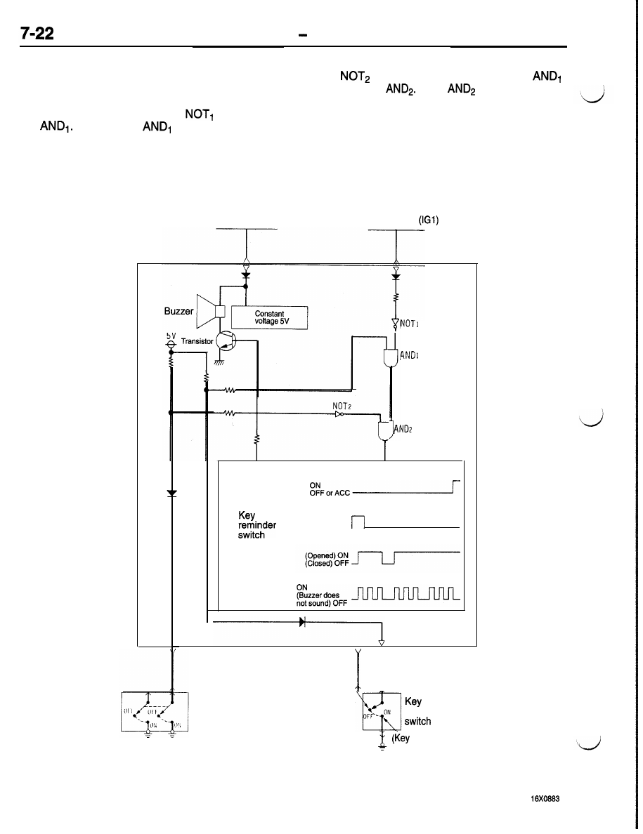
IGNITION KEY REMINDER ALARM FUNCTION
1. When the ignition key is left inserted with the

ignition switch in the OFF or ACC position, the
H signals of the key reminder switch and the
ignition switch inverted by 

 are input to

by 

 and the H signal output from 

are input to 

 Then 

 outputs H signal

to cause the detector circuit to operate.

3.

 As a result, 

 outputs H signal.

The buzzer output causes the transistor to be

2.

When the driver’s door is opened (door switch

alternately ON and OFF, and the buzzer sounds

ON), the H signal of the door switch inverted

intermittently to remind the driver that the ignition
key has not been removed.

ETACS-EC1

Fusible link

Ignition switch 

Detection circuit

Ignition

switch

(Key removed) ON

(Key inserted) OFF

Driver’s

door

switch

Buzzer
output

(Buzzer sounds)

Driver’s door
switch

(Key inserted)

reminder

 removed)

EQUIPMENT   ETACS

IGNITION SWITCH ILLUMINATION LIGHT TIMER FUNCTION
1.

When the ignition switch is in the OFF or ACC

position, the H signal of the ignition switch in-

verted by 

 is input to 

 and 

2.

When the driver’s door is opened (door switch
ON), the H signal of the door switch inverted

by 

 is input to 

 As a result, 

outputs H signal to cause the timer circuit to
operate.

3.

Accordingly, when the H signal output from the
timer is input to 

 the output signal from

 changes to H signal which causes the

transistor to be ON for 10 seconds to light the

ignition switch illumination light.

Ignition switch
illumination light

4. When the ignition switch is placed in the ON

position during operation of the timer, the L sig-
nal of the ignition switch inverted by 

 is

input to 

 As a result, 

 outputs L

signal which causes the transistor to be OFF,
and the ignition switch illumination light goes
out immediately.

NOTE
Even if the driver’s door is opened and closed (door

switch caused to be ON and OFF) while the timer

is in operation, no input signal is accepted.

Fusible link

Ignition switch 

4

Timer circuit

I g n i t i o n   O N

switch


Driver‘s

door

(Opened) ON

  ( C l o s e d )   O F F  

,

Timer

H signal (ON)

 signal 

(OFF)


ETACS-ECU

 Driver’s door


   switch


EQUIPMENT   ETACS

DOME LIGHT AND FOOT LIGHT DIMMING TIMER FUNCTION

1. When any of the doors or tailgate is opened

(door switch ON or luggage compartment light
switch* ON) with the dome light switch in the
DOOR position (vehicles without sunroof) or
OFF position (vehicles with sunroof), the dome
light will light ON.

NOTE

When the front doors or tailgate is opened, the
foot light comes on regardless of the light switch

position.

2.

When all the doors and tailgate are closed with
the ignition switch in the OFF or ACC position

(door switch OFF and luggage compartment
light switch* OFF), the H signal of the ignition

switch inverted by NOT and the H signal of
the door switch are input to AND. As a result,

Fusible link

I

Ignition switch 

I

ETACS-EC1J

AND outputs H signal which operates the timer
circuit.

3.

The timer output provides signals which slowly

reduce the voltage to the transistor in approxi-
mately six seconds , thereby dimming the dome
light and foot light.

4. When the ignition switch is placed in the ON

position during operation of the timer, the L sig-
nal of the ignition switch inverted by NOT is
input to AND. As a result, AND outputs L signal,
and the timer circuit stops operation. The dome
light and foot light, therefore, goes out immedi-
ately without dimming.

NOTE

 On vehicles with theft-alarm system, this switch

is the 

 switch.

Ignition switch

Timer circuit


Door switch

(Opened) ON

( C l o s e d )  

Timer output

(Light ON)

approx. 6 

I

-

-

-

-

-

-

Transistor

Door
switch (LH)

Dome light

  < W i t h

 sunroof>

Foot
light

 or 

switch

   ETACS

DEFOGGER TIMER FUNCTION
1. When the ignition switch is turned to the ON

position, the H signal of the ignition switch and
the H signal of the constant voltage are input
to AND. As a result, AND outputs H signal.

2.

When the defogger switch is placed in the ON
position, the H signal inverted by NOT is input
to timer circuit to activate the timer circuit.

3. Since the defogger switch (auto reset switch)

placed in the ON position is automatically reset
to the OFF state, the L signal which is opposite
to the signal in Item (2) is input to the timer
circuit after the switch has been caused to be
ON, but the timer keeps on operating.

The timer output causes the transistor to be
ON for   minutes. The defogger relay is also
placed in the ON position to operate the defog-
ger.
When the ignition switch is placed in the OFF
position or when the defogger switch is placed

in the ON position again during operation of

the timer, the H signal is input to the timer circuit
again. As a result, the timer circuit stops operat-

ing, and the transistor is forced to the OFF state.

The defogger relay is also placed in the OFF

oosition and the defogger stops operating.

Ignition switch

NOT

Timer circuit

Ignition ON

switch

OFF 


T i m e r   O N  
output

O F F  

11 mins 11 mins 11 mins

Transistor

OFF


ETACS-ECU

Fusibl

Ignition switch

 link

-

-

1

Defogger
relay


Content   ..  89  90  91  92   ..