Mitsubishi Eclipse. Technical Information Manual (1994) - part 52
 

  Index      Mitsubishi     Mitsubishi Eclipse. Technical Information Manual (1994)


Search            


Content   ..  50  51  52  53   ..


Mitsubishi Eclipse. Technical Information Manual (1994) - part 52


POWER TRAIN   Automatic Transaxle

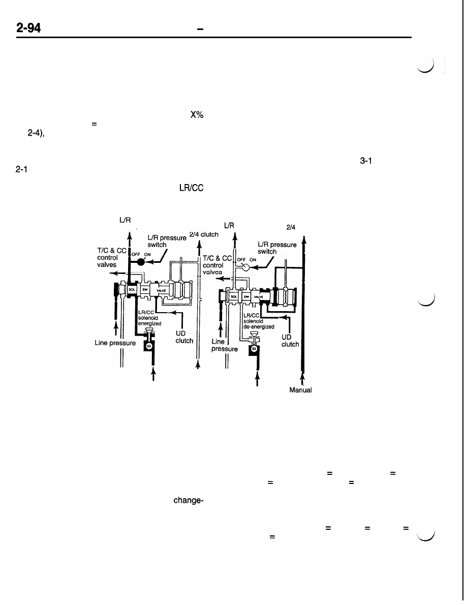
Solenoid Switch Valve Control Logic
This valve protects against the inadvertent applica-

tion of LR clutch in second, third, or fourth gear

ranges. When shifting to first gear, the Solenoid

Switch Valve (SSV) must be in the downshifted posi-
tion or action must be taken to shift the SSV into
the downshifted position. As long as any of three
pressures (2-4, OD, or UD) are greater than 
of line pressure (X   60% for UD and OD, 70%

for 

 the SSV will remain upshifted. To confirm

that the SSV has downshifted, both the LR solenoid
and LR pressure switch must be high (voltage value
seen by TCM). To downshift the valve for 3-1 or

 shifts, shift logic will briefly vent the UD clutch

(shift logic must vent the other two clutches also)

and test for valve motion by eneraizing the 

clutch

solenoid and verifying that the LR pressure switch
turns on.
A SSV diagnostic trouble code will only be stored
if the transaxle operating temperature range is hot,
and the malfunction occurs at least three times.
The fault counter is reset during the start routine.
Under certain conditions, such as very cold fluid
temperatures, it is possible that the SSV valve may
not move as quickly as it normally would at operating
temperature. This slow response may occasionally
result in a second gear launch or a change mind

shift to second gear from a 2-l or 

 shift. No

diagnostic trouble code will be set if the transaxle
operating temperature range is cold.

 clutch

 clutch

I

Manual

Manual

valve

valve

Clutch Apply Status
To execute the shift logic, the TCM must maintain
a continuous record of each clutch element apply
status. This is done by tracking the instantaneous
fluid volumes in each clutch circuit. Instantaneous
fluid volumes are tracked using predetermined flow

rates and learned “clutch fill volumes”. This is partic-
ularly useful for closely-spaced shifts or 

mind shifts.

Learned clutch fill volumes represent the volume

of fluid that is required to stroke a clutch piston
to the point where zero clutch pack clearance is
obtained. The clutch fill volume learn value is the

fill volume 

without stroking the accumulator or pick-

ing up any torque load on the clutch. This learned

fill volume is updated for each clutch element as

it wears and clutch pack clearance increases.

Manual
valve

valve

The Clutch Volume Index (CVI) display of the scan
tool (MUT-II) can be used to view learned clutch
fill volumes for each clutch. The normal range for
clutch fill volumes are LR   35 to 85, OD   75
to 150, 2-4 

20 to 77, and UD   24 to 70.

If the battery feed is disconnected from the TCM,

the learned clutch fill volumes will be lost, and initial
values will be substituted until correct values can

be re-learned. Shifting may be somewhat harsh.

The initial values are; LR   64, OD   89, 2-4 
48, and UD   45.
A transmission which has experienced a sudden
clutch failure may not be capable of learning the
correct values. A road test of a transaxle with this
condition may exhibit an upshift runaway condition,

but have acceptable clutch fill volumes.

POWER TRAIN

 - Automatic Transaxle

2-95

Normal Shutdown Routine

When the ignition switch is turned off (column lock,

key out position), the TCM will go through a specific
shutdown routine.
For the first twenty minutes after ignition off, the
CPU remains in the “awake” mode. In tills off-time

tracking mode, the TCM continues to perform certain
functions such as predicting fluid temperature cal-
culations.

Longer off-time tracking is currently prohibited due

to battery drain concerns since the CPU remains

powered up during this time.
After 20 minutes have elapsed, the CPU will switch
into a Sleep mode. In this mode the TCM does
not perform any functions and its Keep Alive Memory
uses only a very small amount of current.
The TCM uses a “Keep Alive Memory” that must
always remain connected to the battery voltage 

Fail-Safe Routine

The TCM is designed and programmed with what

is called a fail-safe routine. This routine constantly
monitors and checks all input and control features

for normal operation. The TCM uses inputs from
the PCM, transmission range and park neutral

switches, input and output speed signals, throttle
position, ignition and pressure switches to determine

the desired outputs. The primary outputs are to
the four solenoid valves which control the transaxle

clutches. Changes in these solenoid outputs can

When a failure has been identified which prevents
continued safe transaxle operation, the TCM eventu-
ally goes into limp-in by turning off all of the sole-

noids. This provides for shift lever controlled opera-

tion of SECOND GEAR, NEUTRAL, REVERSE,

and PARK. The TCM has logic to ensure the limp-in
results in an ORDERLY SHUTDOWN. Certain fail-
ures will prevent an orderly shutdown, and an IM-
MEDIATE SHUTDOWN will occur.
Orderly Shutdown -A Shutdown routine is activated
with certain failures prior to opening the transmission
control relay. The result of an orderly shutdown is
dependent on the operating condition at the time
of the failure. If the transaxle is in Park, Reverse,

Neutral, or Second Gear, there is no additional action
needed by the TCM. The transmission control relay
is opened immediately because the power off state

of the transaxle has already been achieved.

If the transaxle is in first gear, then the shutdown

sequence (default to second gear) begins immedi-
ately.

If the transaxle is in third or fourth Gear above 45

 mph, then the current gear range is maintained

to prevent the possibility of causing high engine

rpm and/or 

engine braking.

ply. If the TCM is disconnected, the “Keep Alive
Memory” will be lost. This memory is where 
tic trouble codes and other learned values are
stored. These values may be clutch apply and re-
lease rates and clutch fill volumes. If the TCM is
disconnected from its direct battery voltage supply,
initial stored values are substituted for the erased
learned values when the CPU is re-initialized. These
values will then be updated as new values are
learned when operating the transaxle.
A code 12 will also be stored on any initialization
following a direct battery feed disconnection. Code

12 lets you know that a direct battery disconnection

has occurred.

result in changes in clutch pressures, pressure
switch states and input speeds. These changes
become the new input. If they are not as desired,

then the solenoid output is adjusted accordingly.
This feed-back control is referred to as a closed

loop system and is an integral part of fail-safe.

NOTE

The purpose of this section is to cover fail-safe

logic. Refer to the Fault Code Explanation section

for diagnostic information and probable causes.

The actual shutdown sequence to second Gear be-
gins once the vehicle speed drops below 45 mph.
The exception to this rule is when the vehicle is
at high speed and develops a solenoid circuit error.

If this occurs, a temporary “neutral” state is gener-

ated by venting all clutches to avoid incorrect clutch
combinations   see Codes 41 to 44.

The shutdown sequence reduces the possibility of

having engine flare-up or clutch overlap (three

clutches applied) as the transaxle defaults to second
gear. This is accomplished by releasing the non
second gear clutches slightly before the transmis-
sion control relay is opened. This will occur when
the throttle angle is less than approximately 
full open. At greater throttle angles, the transmission
control relay is immediately opened. This is done
because second gear clutches typically apply faster
than the non second gear clutches. Again, the pur-

pose for this sequence of events is to prevent more

than the correct number of clutches from being ap-

plied at the same time during moderate throttle
angles and to prevent engine flare at higher throttle
openings.

POWER TRAIN   Automatic Transaxle

Immediate Shutdown -To cause an immediate 

down to occur, all solenoids are turned off at the
same time. To cause an immediate shutdown the
transmission control relay is opened at the time
of the failure. Default to second gear will take place
from first, third, or fourth gear. The immediate 
down may result in clutch overlap at low to moderate
throttle angles and a temporary engine flare with

heavier throttle angles. An engine braking condition
may also result at high vehicle speeds.

At the end of either shutdown routine, the failure
condition will be recorded in memory. The use of
the scan tool (MUT-II) is required to determine what
the diagnostic trouble code was at the time of the
failure.

INPUTS

PCM 

Speed

signals

Throttle

 Ignition

Power 

TRANSMISSION CONTROL MODULE

I


 I 


  R A M  


OUTPUTS

POWER  TRAIN

 - Automatic Transaxle

DIAGNOSTIC FUNCTION CHART

Diagnostic trouble

Item

code No.

11

Internal control module (watchdog circuit test failure)

12

Battery power was disconnected since last power down

13

Internal control module (watchdog circuit shutdown)

14

Relay always On (relay contacts are welded closed)

15

Relay always Off (relay contacts are stuck open)

16

Internal control module (ROM checksum failure)

17

Internal control module (RAM checksum failure)

18

Engine speed sensor circuit

19

CCD bus communication with SBEC

20

Switched battery

21

Pressure switch circuit

OD

2-4

24

LR

27

28

Check shifter signal

All

Throttle position signal

31

Hydraulic pressure switch

 OD

 2-4


35

Check ATF level

36

Fault immediately after a shift

37

Solenoid switch valve latched in the LU position

Lockup control out of range

41

Solenoid circuit error

LR

 2-4

43

OD

44

UD

45

Internal control module (engine model EEPROM cell failure)


Content   ..  50  51  52  53   ..