Mitsubishi Colt Ralliart. Manual - part 761
 

  Index      Mitsubishi     Mitsubishi Colt Ralliart - service repair manual


Search            


Content   ..  759  760  761 


Mitsubishi Colt Ralliart. Manual - part 761


ON-VEHICLE SERVICE

MULTIPORT FUEL INJECTION (MPI) <4G1>

13B-369

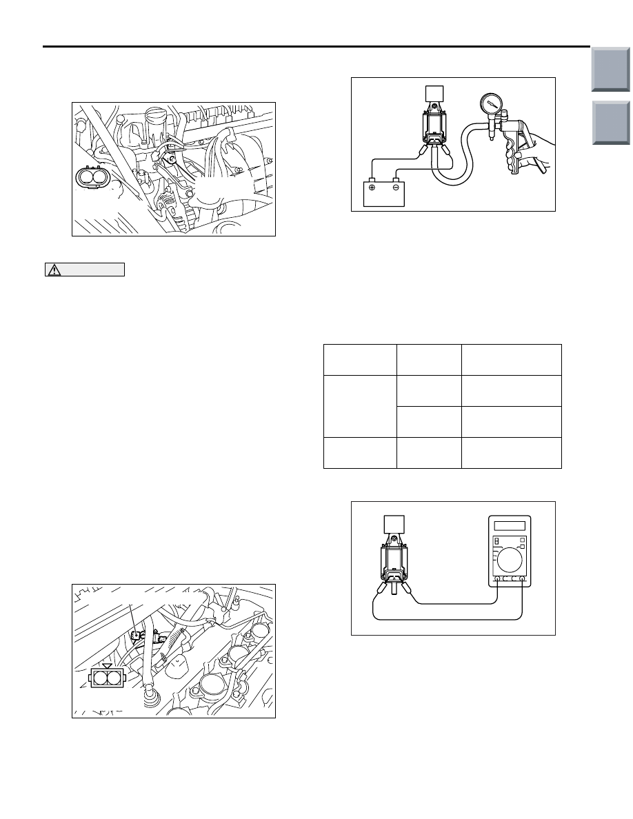
OIL FEEDER CONTROL VALVE CHECK

M1131053800061

OPERATION CHECK

1. Disconnect the oil feeder control valve connector.

CAUTION

To prevent the coil from burning, keep the dura-
tion of the voltage application as short as possi-
ble.
2. Apply battery voltage to the terminals of the 

connector at the oil feeder control valve, and 
make sure the oil feeder control valve makes a 
clicking sound.

MEASUREMENT OF RESISTANCE 
BETWEEN TERMINALS

1. Disconnect the oil feeder control valve connector.
2. Measure the resistance between the terminals of 

the connector at the oil feeder control valve.

Standard value: 6.9 

 7.9  (at 20°C)

3. If resistance is outside the standard value, replace 

the oil feeder control valve.

FUEL PRESSURE SOLENOID VALVE 
CHECK

M1131053700031

OPERATION CHECK

1. Remove the vacuum hose from the solenoid 

valve.

2. Disconnect the harness connector.

3. Connect the hand vacuum pump to nipple A of the 

solenoid valve.

4. Use a jumper wire to connect the solenoid 

terminals to the battery terminals.

5. Interrupt the jumper wire on the battery (

−) 

terminal side and apply negative pressure to 
check for airtightness.

Standard value:

COIL RESISTANCE CHECK

1. Measure the resistance between terminals of the 

solenoid valve.

Standard value: 29 

 35  (at 20 °C)

AK402207

1 2

AC

Oil feeder 
control valve

Oil feeder 
control valve side
connector

AK402131

1

2

AC

Equipment side
connector

Fuel pressure solenoid valve

Jumper wire Condition 

of nipple B

Normal condition

Disconnect

Open

Negative pressure 
leaks

Blocked

Negative pressure 
is retained

Connect

Open

Negative pressure 
is retained

AK200256AC

A

B

Battery

AK200257

Main

Index

Group

TOC

INJECTOR

MULTIPORT FUEL INJECTION (MPI) <4G1>

13B-370

INJECTOR

REMOVAL AND INSTALLATION

M1131007101772

CAUTION

When the fuel injector replacement is performed, use the M.U.T.-III to initialise the learning value 
(Refer to GROUP 00, Precautions Before Service 

 Initialisation Procedure for Learning Value in MPI 

Engine 

P.00-20

).

Pre-removal Operation
• Fuel Discharge Prevention (Refer to 

P.13B-360

).

• Engine Cover Removal (Refer to GROUP 11C, Camshaft 

and Valve Stem Seal 

P.11C-20

).

• Air Cleaner Assembly Removal (Refer to GROUP 15, Air 

Cleane

P.15-6

).

• Air Pipe B Removal (Refer to GROUP 15, Intercooler 

P.15-8

).

Post-installation Operation
• Air Pipe B Installation (Refer to GROUP 15, Intercooler 

P.15-8

).

• Air Cleaner Assembly Installation (Refer to GROUP 15, 

Air Cleaner 

P.15-6

).

• Fuel Leakage Inspection
• Engine Cover Installation (Refer to GROUP 11C, Cam-

shaft and Valve Stem Seal 

P.11C-20

).

AC403099

1

1

12 ± 1 N·m

10

N

13

12

AB

7

11

14

3

4

2

8

9

2

N

6

5

12 ± 1 N·m

Apply engine oil to
the O-ring before
installation.

Removal steps 

1.

Fuel injector connector

2.

Control harness clamp connection

<<A>> >>C<<

3.

Fuel high-pressure hose 
connection

4.

Fuel return hose connection

>>A<<

5.

Fuel pressure regulator

6.

O-ring

7.

Fuel hose

<<B>> >>B<<

8.

Fuel delivery pipe and fuel injector 
assembly

9.

Fuel delivery pipe insulator

>>A<<

10. Fuel injector assembly
11. O-ring
12. Fuel injector insulator
13. Fuel injector
14. Fuel delivery pipe

Removal steps (Continued)

Main

Index

Group

TOC

INJECTOR

MULTIPORT FUEL INJECTION (MPI) <4G1>

13B-371

REMOVAL SERVICE POINTS
<<A>> FUEL HIGH-PRESSURE HOSE 
DISCONNECTION

1. Remove the stopper.

2. Raise the retainer, and pull out the fuel 

high-pressure hose.
NOTE: If the retainer comes off, install it securely 
after pulling out the fuel high-pressure hose.

<<B>> FUEL DELIVERY PIPE AND FUEL 
INJECTOR ASSEMBLY REMOVAL

CAUTION

Do not drop the fuel injector.
Remove the fuel delivery pipe with the fuel injector 
assembly attached to it.

INSTALLATION SERVICE POINTS
>>A<< FUEL INJECTOR ASSEM-
BLY/FUEL PRESSURE REGULATOR 
INSTALLATION

CAUTION

Do not let the engine oil get into the fuel delivery 
pipe will be damaged.
1. Apply a drop of new engine oil to the O-ring.
2. Turn the fuel injector assembly and fuel pressure 

regulator to the right and left to install to the fuel 
delivery pipe. Be careful not to damage the 
O-ring. After installing, check that the item turns 
smoothly.

3. If it dose not turn smoothly, the O-ring may be 

trapped, remove the item, re-install it into the fuel 
delivery pipe and check again.

4. Tighten the fuel pressure regulator to the specified 

torque.

Tightening torque: 12 

± 1 N

>>B<< FUEL DELIVERY PIPE AND FUEL 
INJECTOR ASSEMBLY INSTALLATION

CAUTION

Securely bring the insulator into contact with the 
injector to prevent air leak from the insulator 
area.

Be sure that there is no clearance between the insu-
lator area and the injector, and install them to the cyl-
inder head.

AC402313AB

Fuel high-pressure hose

Stopper

AC402314AC

Fuel high-pressure
hose

Retainer

AC601238AB

Injector

Insulator

Main

Index

Group

TOC

INJECTOR

MULTIPORT FUEL INJECTION (MPI) <4G1>

13B-372

>>C<< FUEL HIGH-PRESSURE HOSE 
CONNECTION

CAUTION

• After connecting the fuel high-pressure hose, 

check that it has been securely installed by 
slightly pulling in the removal direction. At 
this time, also check that there is approxi-
mately 3-mm play.

• Do not let the engine oil get into the fuel deliv-

ery pipe will be damaged.

Apply a small amount of new engine oil to the fuel 
delivery pipe, and install the fuel high-pressure hose 
to the fuel delivery pipe.

AC208465AE

3 mm

Fuel high-pressure hose

Fuel delivery pipe

Main

Index

Group

TOC


Content   ..  759  760  761