Mitsubishi Colt Ralliart. Manual - part 676
 

  Index      Mitsubishi     Mitsubishi Colt Ralliart - service repair manual


Search            


Content   ..  674  675  676  677   ..


Mitsubishi Colt Ralliart. Manual - part 676


TROUBLESHOOTING

MULTIPORT FUEL INJECTION (MPI) <4G1>

13B-29

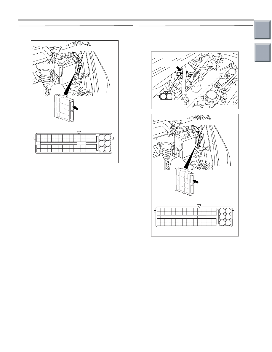
STEP 8. Connector check: A-114 engine-ECU 
connector

Q: Is the check result normal?

YES : 

Go to Step 9 .

NO : 

Repair or replace.

STEP 9. Check harness between A-136 (terminal 
No. 2) fuel pressure solenoid valve connector 
and A-114 (terminal No. 57) engine-ECU 
connector.

• Check output line for damage.

Q: Is the check result normal?

YES : 

Go to Step 10 .

NO : 

Repair.

AK402745

6

4

2

5

3

1

9

7

8

10

11

12

13

14

15

16

17

18

19

20

21

22

23

24

25

26

27

28

29

30

31

32

33

34

35

36

37

38

39

40

41

42

43

44

45

46

47

48

49

50

51

52

53

54

55

56

57

58

59

60

61

62

63

64

65

66

L

AF

A-114

Connector: 

A-114

Harness side connector

Engine-ECU

Battery

AK402120

1

2

AC

Connector: A-136

Harness side 
connector

A-136(B)

AK402745

6

4

2

5

3

1

9

7

8

10

11

12

13

14

15

16

17

18

19

20

21

22

23

24

25

26

27

28

29

30

31

32

33

34

35

36

37

38

39

40

41

42

43

44

45

46

47

48

49

50

51

52

53

54

55

56

57

58

59

60

61

62

63

64

65

66

L

AF

A-114

Connector: 

A-114

Harness side connector

Engine-ECU

Battery

Main

Index

Group

TOC

TROUBLESHOOTING

MULTIPORT FUEL INJECTION (MPI) <4G1>

13B-30

STEP 10. Check harness between A-136 (terminal 
No. 1) fuel pressure control solenoid valve 
connector and B-106 (terminal No. 4) engine 
control relay connector.

NOTE: Before checking harness, check intermediate 
connectors A-17 and B-112, and repair if necessary.

• Check power supply line for damage.

Q: Is the check result normal?

YES : 

Go to Step 11 .

NO : 

Repair.

STEP 11. M.U.T.-III actuator test

• Item 09: Fuel pressure solenoid valve

OK: Operating sound can be heard and the 
valve vibrates.

Q: Is the check result normal?

YES : 

Intermittent malfunction (Refer to GROUP 

00 

− How to Use Troubleshooting/Inspection 

Service Points 

− How to Cope with 

Intermittent Malfunctions 

P.00-13

).

NO : 

Replace engine-ECU.

AK402120

1

2

AC

Connector: A-136

Harness side 
connector

A-136(B)

3

2

1

4

AK402084

J/B side 
connector

B-106

Connector: B-106
J/B (front side)

AC

Main

Index

Group

TOC

TROUBLESHOOTING

MULTIPORT FUEL INJECTION (MPI) <4G1>

13B-31

Code No. P0100: Air Flow Sensor System

AK402713

3

1

2

4

1

2

3 4

R

92 93 94 95969798

77 78 79 808182838485868788899091

99

100

107 108 109 110 111112113114115116117118119120121
122 123 124 125126127128129130131132133134135136

101102103104105106

71 72

73 74

75 76

Y-L

Air flow sensor

Engine-ECU 

90

3

102

2

4

A-34

AE

Wire colour code
B: Black  LG: Light green  G: Green  L: Blue  W: White  Y: Yellow  SB: Sky blue  BR: Brown  O: Orange  GR: Gray
R: Red  P: Pink  V: Violet  P: Purple

Air Flow Sensor Circuit

J/B

Engine
control
relay

4

2

3

1

6

To engine-ECU

R

B-106

B-112

1

1

R

Fusible link

16

20A

B-108

B

A-08

5 V

Main

Index

Group

TOC

TROUBLESHOOTING

MULTIPORT FUEL INJECTION (MPI) <4G1>

13B-32

OPERATION

• Power is supplied to the air flow sensor (terminal 

No. 2) through engine control relay (terminal No. 
4), and the air flow sensor (terminal No. 4) is 
earthed to the engine-ECU (terminal No. 102).

• The sensor output signal is input to the 

engine-ECU (terminal No. 90) from the air flow 
sensor output terminal (terminal No. 3).

FUNCTION

• The air flow sensor outputs a current correspond-

ing to the intake of air.

• In response to the air flow sensor output and 

engine speed signal, the engine-ECU determines 
the basic injection time for the injectors.

TROUBLE JUDGEMENT

Check Condition

• 3 seconds later from when ignition switch is in 

ON position.

• While engine running

Judgement Criterion

• Sensor output voltage is less than 0.2 V for 4 sec-

onds.

Or

• Sensor output voltage is more than 4.9 V for 4 

seconds.

PROBABLE CAUSES

• Failed air flow sensor

• Open/short circuit in air flow sensor circuit or 

loose connector contact

• Failed engine-ECU

DIAGNOSIS PROCEDURE

STEP 1. M.U.T.-III data list

• Refer to Data List Reference Table 

P.13B-335

.

a. Item 12: air flow sensor

Q: Is the check result normal?

YES : 

Intermittent malfunction (Refer to GROUP 

00 

− How to Use 

Troubleshooting/Inspection Service Points 

− 

How to Cope with Intermittent Malfunctions 

P.00-13

).

NO : 

Go to Step 2 .

STEP 2. Connector check: A-34 air flow sensor 
connector

Q: Is the check result normal?

YES : 

Go to Step 3 .

NO : 

Repair or replace.

STEP 3. Perform voltage measurement at A-34 air 
flow sensor connector.

• Disconnect connector, and measure at harness 

side.

• Ignition switch: ON

• Voltage between terminal No. 2 and earth.

OK: System voltage

Q: Is the check result normal?

YES : 

Go the Step 5 .

NO : 

Go the Step 4 .

AK402083

2

1

3

4

Connector: A-34

Harness side 

connector

A-34 (GR)

AC

AK402083

2

1

3

4

Connector: A-34

Harness side 

connector

A-34 (GR)

AC

Main

Index

Group

TOC


Content   ..  674  675  676  677   ..