Mitsubishi Colt Ralliart. Manual - part 653
 

  Index      Mitsubishi     Mitsubishi Colt Ralliart - service repair manual


Search            


Content   ..  651  652  653  654   ..


Mitsubishi Colt Ralliart. Manual - part 653


CRANKSHAFT OIL SEAL

ENGINE MECHANICAL <4G1>

11C-32

REMOVAL SERVICE POINT
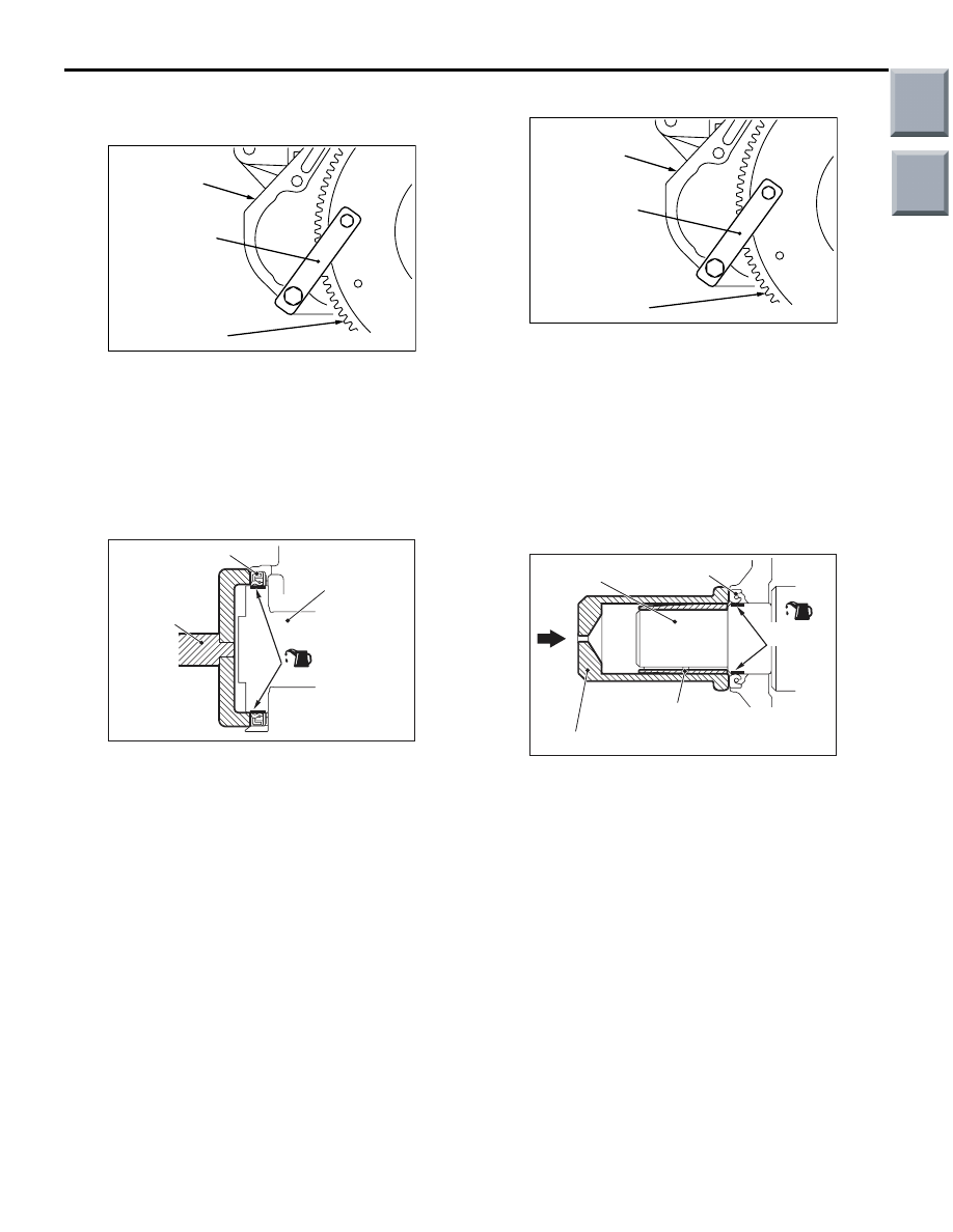
<<A>> FLYWHEEL BOLT REMOVAL

AK305392AB

MD998781

Cylinder block

Flywheel

1. Use special tool flywheel stopper (MD998781) to 

secure the flywheel.

2. Remove the flywheel bolts.

INSTALLATION SERVICE POINTS
>>A<< CRANKSHAFT REAR OIL SEAL 
INSTALLATION

AC102328AC

Oil seal

MD998011

(Engine oil)

Crankshaft

1. Apply a small amount of new engine oil to the 

entire inner diameter of the oil seal lip.

2. Use following special tool crankshaft rear oil seal 

installer (MD998011) to press-fit the oil seal.

>>B<< FLYWHEEL BOLT INSTALLATION

AK305392AB

MD998781

Cylinder block

Flywheel

1. Use special tool flywheel stopper (MD998781) to 

secure the flywheel in the same manner as 
removal.

2. Tighten the flywheel bolts to the specified torque 

in a crisscross pattern.

Tightening torque: 132 

± 5 Nm

>>C<< CRANKSHAFT FRONT OIL SEAL 
INSTALLATION

AC102329AD

MD998306

MB991962

Oil seal

Crankshaft

(Engine oil)

(Oil applied to the
circumference)

1. Apply a small amount of engine oil to the outer 

diameter of special tool crankshaft front oil seal 
guide (MB991962) and install it to the crankshaft.

2. Apply a small amount of engine oil to the entire 

inner diameter of the oil seal lip.

3. Use special tool crankshaft front oil seal installer 

(MD998306) to press-fit the oil seal.

Main

Index

Group

TOC

CRANKSHAFT OIL SEAL

ENGINE MECHANICAL <4G1>

11C-33

>>D<< TIMING BELT TRAIN 
SPACER/CRANKSHAFT ANGLE 
SENSING BLADE/TIMING BELT TRAIN 
SPRING PIN/CRANKSHAFT CAMSHAFT 
DRIVE SPROCKET INSTALLATION

AC207647

: Clean and degrease

AB

Timing belt train
spring pin

Engine front

Crankshaft camshaft
drive sprocket

Crankshaft angle
sensing blade

Timing belt
train spacer

Crankshaft

1. Clean and degrease the installation side of the 

crankshaft camshaft drive sprocket, the 
crankshaft angle sensing blade, the timing belt 
train spacer and the crankshaft.

NOTE: De-grease to prevent drop in friction factor 
in the presser area due to grease.

AC207648AB

Timing belt train
spring pin

Engine front

Crankshaft camshaft
drive sprocket

Crankshaft angle
sensing blade

Timing belt
train spacer

Crankshaft

2. Install the crankshaft camshaft drive sprocket, the 

timing belt train spring pin, the crankshaft angle 
sensing blade and the timing belt train spacer to 
the crankshaft. Then install the crankshaft in the 
direction shown.

Main

Index

Group

TOC

CYLINDER HEAD GASKET

ENGINE MECHANICAL <4G1>

11C-34

CYLINDER HEAD GASKET

REMOVAL AND INSTALLATION

M1112004002037

Pre-removal Operation
• Fuel Line Pressure Reduction [Refer to GROUP 13B, 

On-vehicle Service 

− Fuel Pump Connector Disconnection 

(How to Reduce Pressurized Fuel Lines) 

P.13B-360

].

• Engine Coolant Draining (Refer to GROUP 14, On-vehicle 

Service 

− Engine Coolant Replacemen

P.14-6

).

• Engine Oil Draining (Refer to GROUP 12, On-vehicle 

Service 

− Engine Oil Replacement 

P.12-4

).

• Inlet Manifold Removal (Refer to GROUP 15, Inlet Mani-

fold 

P.15-12

).

• Water Pump Inlet Pipe Removal (Refer to GROUP 14, 

Water Hose and Water Pipe 

P.14-18

).

• Ignition Coil Removal (Refer to GROUP 16, Ignition Sys-

tem 

− Ignition Coil 

P.16-37

).

• Valve Timing Belt Removal (Refer to 

P.11C-37

).

• Rocker Cover Assembly Removal (Refer to 

P.11C-20

).

Post-installation Operation
• Rocker Cover Assembly Installation (Refer to 

P.11C-20

).

• Valve Timing Belt Installation (Refer to 

P.11C-37

).

• Ignition Coil Installation (Refer to GROUP 16, Ignition 

System 

− Ignition Coil 

P.16-37

).

• Water Pump Inlet Pipe Installation (Refer to GROUP 14, 

Water Hose and Water Pipe 

P.14-18

).

• Inlet Manifold Installation (Refer to GROUP 15, Inlet Man-

ifold 

P.15-12

).

• Engine Oil Refilling (Refer to GROUP 12, On-vehicle 

Service 

− Engine Oil Replacement 

P.12-4

).

• Engine Coolant Refilling (Refer to GROUP 14, On-vehicle 

Service 

− Engine Coolant Replacement 

P.14-6

).

• Fuel Leak Check

AC402493

30 ± 3 N·m

1

N

 (Engine oil)

9.0 ± 2.0 N·m

<Cold engine>
49 ± 2 N·m to

 0 N·m to 

20 ± 2 N·m to

 +90˚ to +90˚

2

3

4

5

6

7

8

9

10

11

N

N

42 ± 2 N·m

AD

Removal steps 

Engine mounting insulator (Refer to 
GROUP 32, Engine Mounting 

P.32-6

).

1.

Noise condenser

2.

Heater piping hose connection

Alternator brace (Refer to GROUP 
16, Charging System 

− Alternator 

P.16-14

).

3.

Eye bolt

4.

Gasket

Removal steps (Continued)

Main

Index

Group

TOC

CYLINDER HEAD GASKET

ENGINE MECHANICAL <4G1>

11C-35

REMOVAL SERVICE POINT
<<A>> CYLINDER HEAD BOLTS 
REMOVAL

AC207639 AB

MB991653

Engine front

Use special tool cylinder head bolt wrench 
(MB991653) to loosen the cylinder head bolts in two 
or three steps in the order of the numbers shown in 
the illustration.
NOTE: If the cylinder head bolts cannot be pulled out 
due to the washer being trapped in the valve spring, 
raise the bolt slightly, then remove it while holding it 
by using a magnet.

INSTALLATION SERVICE POINTS
>>A<< CYLINDER HEAD GASKET 
INSTALLATION

CAUTION

Do not allow any foreign materials get into the 
coolant passages, oil passages and cylinder.
1. Degrease the cylinder head gasket mounting 

surface.

AC403645AF

Identification mark "1.5"

Inlet side

2. Assemble to the cylinder block so the cylinder 

head gasket identification mark of "1.5" is at the 
top surface and on the inlet side.

5.

Eye bolt

6.

Gasket

7.

Oil feeder control valve pipe

8.

Filter

<<

A

>>

>>

B

<<

9.

Cylinder head bolts

10. Cylinder head assembly

>>

A

<<

11. Cylinder head gasket

Removal steps (Continued)

Main

Index

Group

TOC


Content   ..  651  652  653  654   ..