Mitsubishi Colt Ralliart. Manual - part 632
 

  Index      Mitsubishi     Mitsubishi Colt Ralliart - service repair manual


Search            


Content   ..  630  631  632  633   ..


Mitsubishi Colt Ralliart. Manual - part 632


TROUBLESHOOTING

ACTIVE STABILITY CONTROL SYSTEM (ASC)

35C-73

STEP 2. Diagnosis code recheck after resetting 
CAN bus lines

Q: Is the diagnosis code No. C1861 set?

YES : 

Go to Step 3.

NO : 

This diagnosis is complete.

STEP 3. Battery terminal voltage measurement
(1) Start the engine.
(2) Measure the voltage between the positive and 

negative battery terminals.

OK: 10 V or more

Q: Is the check result normal?

YES : 

Go to Step 4.

NO : 

Diagnose the charging system. (Refer to 
GROUP 16 

− On-vehicle Service 

P.16-6

.)

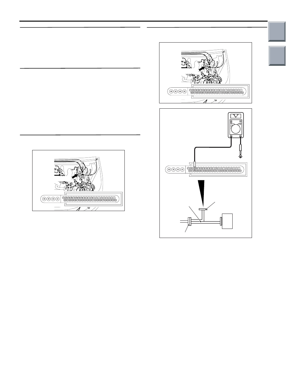
STEP 4. Connector check: A-05 ASC-ECU 
connector

Q: Is the check result normal?

YES : 

Go to Step 5.

NO : 

Repair the damaged connector.

STEP 5. Voltage measurement: A-05 ASC-ECU 
connector

(1) Disconnect the connector, connect the ASC 

check harness (Special tool: MB991984) to the 
ASC-ECU side connector and harness-side 
connector, and then measure the voltage at the 
special tool connector side.

(2) Start the engine.
(3) Measure the voltage between the terminal No. 40 

and the body earth.

OK: 10 V or more

Q: Is the check result normal?

YES : 

Go to Step 6.

NO : 

Repair the wiring harness.

AC601083

Connector: A-05

AB

A-05(Black)

Harness side

AC601083

Connector: A-05

AB

A-05(Black)

Harness side

AC601086AC

MB991984

ASC-ECU

Check connector

ASC-ECU harness connector

Main

Index

Group

TOC

TROUBLESHOOTING

ACTIVE STABILITY CONTROL SYSTEM (ASC)

35C-74

STEP 6. Measure the resistance at A-05 ASC-ECU 
connector.

(1) Disconnect the connector, connect the ASC 

check harness (Special tool: MB991984) to the 
harness-side connector, and measure the voltage 
at the special tool connector side.
NOTE: . Do not connect the special tool to 
ASC-ECU.

(2) Measure the resistance between the terminal No. 

43 and the body earth.

OK: Continuity exists (2 

 or less)

Q: Is the check result normal?

YES : . 

Go to Step 7.

NO : . 

Repair the wiring harness.

STEP 7. Diagnosis code recheck
Recheck if the diagnosis code is set.
(1) Erase the diagnosis code.
(2) Ignition switch: LOCK (OFF) position
(3) Start the engine.
(4) Drive the vehicle at 6 km/h or more.

Q: Is the diagnosis code No. C1861 set?

YES : 

Replace the ASC-ECU.

NO : 

Intermittent malfunction (Refer to GROUP 
00 

− How to Cope with Intermittent 

Malfunction 

P.00-13

.)

AC601083

Connector: A-05

AB

A-05(Black)

Harness side

AC601085AI

MB991984

ASC-ECU

Check connector

ASC-ECU harness connector

Main

Index

Group

TOC

TROUBLESHOOTING

ACTIVE STABILITY CONTROL SYSTEM (ASC)

35C-75

Code No. C1862: Abnormal power supply voltage of G and yaw rate sensor (high voltage)

CAUTION

If there is any problem in the CAN bus lines, an 
incorrect diagnosis code may be set. Prior to this 
diagnosis, always diagnose the CAN bus lines.

DIAGNOSIS CODE SET CONDITIONS

The G and yaw rate sensor monitors the G and yaw 
rate sensor power supply voltage supplied from the 
battery. When the voltage rises up to approximately 
17 V or more, the sensor determines that the trouble 
occurs and sets the diagnosis code.

Current trouble

• Charging circuit failure

• G and yaw rate sensor malfunction

DIAGNOSTIC PROCEDURE

STEP 1. M.U.T.-III CAN bus diagnostics
Use the M.U.T.-III to diagnose the CAN bus lines.

Q: Is the check result normal?

YES : 

Go to Step 3.

NO : 

Repair the CAN bus lines. (Refer to GROUP 
54D 

− Troubleshooting 

P.54D-13

.) On 

completion, go to Step 2.

STEP 2. Diagnosis code recheck after resetting 
CAN bus lines

Q: Is the diagnosis code No. C1862 set?

YES : 

Go to Step 3.

NO : 

This diagnosis is complete.

STEP 3. Battery terminal voltage measurement
(1) Start the engine.
(2) Set the engine speed to approximately 2500 rpm.
(3) Measure the voltage between the positive and 

negative battery terminals.

OK: 16 V or less

Q: Is the check result normal?

YES : 

Go to Step 4.

NO : 

Diagnose the charging system. (Refer to 
GROUP 16 

− On-vehicle Service 

P.16-6

.)

STEP 4. Diagnosis code recheck
(1) Start the engine.
(2) Set the engine speed to approximately 2500 rpm.

Q: Is the diagnosis code No. C1862 set?

YES : 

Replace the G and yaw rate sensor.

NO : 

Intermittent malfunction (Refer to GROUP 
00 

− How to Cope with Intermittent 

Malfunction 

P.00-13

.)

Main

Index

Group

TOC

TROUBLESHOOTING

ACTIVE STABILITY CONTROL SYSTEM (ASC)

35C-76

Code No. C1863: Abnormal power supply voltage of G and yaw rate sensor (low voltage)

CAUTION

If there is any problem in the CAN bus lines, an 
incorrect diagnosis code may be set. Prior to this 
diagnosis, always diagnose the CAN bus lines.

DIAGNOSIS CODE SET CONDITIONS

The G and yaw rate sensor monitors the G and yaw 
rate sensor power supply voltage supplied from the 
battery. When the voltage drops to approximately 8 V 
or less, the sensor determines that the trouble occurs 
and sets the diagnosis code.

Current trouble

• Damaged wiring harness and connectors

• Charging circuit failure

• G and yaw rate sensor malfunction

DIAGNOSTIC PROCEDURE

STEP 1. M.U.T.-III CAN bus diagnostics
Use the M.U.T.-III to diagnose the CAN bus lines.

Q: Is the check result normal?

YES : 

Go to Step 3.

NO : 

Repair the CAN bus lines. (Refer to GROUP 
54D 

− Troubleshooting 

P.54D-13

.) On 

completion, go to Step 2.

STEP 2. Diagnosis code recheck after resetting 
CAN bus lines

Q: Is the diagnosis code No. C1863 set?

YES : 

Go to Step 3.

NO : 

This diagnosis is complete.

G and Yaw Rate Sensor Power Source Circuit

Wire colour code
B : Black     LG : Light green     G : Green     L : Blue     W : White     Y : Yellow     SB : Sky blue
BR : Brown     O : Orange     GR : Grey     R : Red     P : Pink     V : Violet     PU : Purple

G AND 
YAW RATE 
SENSOR

Main

Index

Group

TOC


Content   ..  630  631  632  633   ..