Mitsubishi Colt Ralliart. Manual - part 612
 

  Index      Mitsubishi     Mitsubishi Colt Ralliart - service repair manual


Search            


Content   ..  610  611  612  613   ..


Mitsubishi Colt Ralliart. Manual - part 612


PISTON AND CONNECTING ROD

ENGINE OVERHAUL <4G1>

11D-48

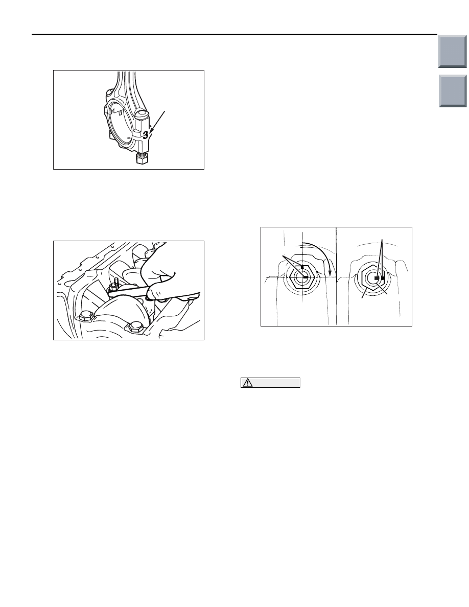
>>F<< CONNECTING ROD CAP 
INSTALLATION

AK402390

Cylinder 
number

AC

1. Install the bearing cap on the connecting rod while 

aligning the marks made during disassembly. If 
the connecting rod is new and has no alignment 
mark, assemble it with the cap such that the both 
bearing locating notches are on the same side as 
shown in the illustration.

AK202821

2. Make sure that the thrust clearance of the 

connecting rod big end is proper.

Standard value: 0.10 

 0.25 mm

Limit: 0.4 mm

>>G<< CONNECTING ROD CAP NUT 
INSTALLATION

1. The connecting rod cap bolts and nuts are 

tightened using the torque-to-yield method. For 
this reason, each bolt to be reused must be 
checked for elongation before installation. 
Whether or not the bolt has been elongated can 
be determined by running a nut with fingers 
through all the threads of the bolt. If the nut does 
not turn smoothly over all the threads, the bolt has 
been elongated and must be replaced.

2. Apply engine oil to the threads and bearing 

surface of each nut before installation.

3. Finger-tighten the nuts on the bolts, then tighten 

the nuts alternately and repeatedly to install the 
cap properly.

4. Tighten the nuts to a torque of 17 

± 2 N⋅m.

AK202543

Paint marks

Nut

90˚ to 94˚

Paint marks

AB

Bolt

5. Make a paint mark on the head of each nut.
6. Make a paint mark on the bolt at a point 90

° to 

94

° away from the paint mark made on the nut in 

the tightening direction.

CAUTION

• If the tightening angle is less than 90°, ade-

quate tightness could not be assured.

• If the tightening angle exceeds 94°, loosen 

the nut completely and then perform the tight-
ening procedure again beginning with the 
first step.

7. Turn the nut 90

° to 94° to bring the mark on the 

nut into alignment with that on the bolt.

Main

Index

Group

TOC

PISTON AND CONNECTING ROD

ENGINE OVERHAUL <4G1>

11D-49

INSPECTION

M1113008500848

PISTON RING

AK202787

1. Measure the clearance between each piston ring 

and its groove. If the limit is exceeded, replace the 
ring or piston, or both.

Standard values:

No. 1 ring 0.03 

 0.07 mm

No. 2 ring 0.02 

 0.06 mm

AK202788

Force ring down 
with piston

End gap

Piston ring

AB

2. Install the piston ring into the cylinder bore and 

force it down with the head of the piston until the 
ring becomes right-angled to the cylinder wall. 
Then, measure the end gap of the ring with a 
thickness gauge. If the end gap is excessive, 
replace the piston ring.

Standard values:

No. 1 ring 0.15 

 0.30 mm

No. 2 ring 0.30 

 0.45 mm

Oil ring 0.20 

 0.50 mm

Limits:

No. 1 ring 0.8 mm
No. 2 ring 0.8 mm
Oil ring 1.0 mm

CRANKSHAFT PIN OIL CLEARANCE 
(PLASTIC GAUGE METHOD)

1. Wipe off oil from the crankshaft pin and 

connecting rod bearing.

2. Cut a piece of plastic gauge whose length is 

equivalent to the width of the bearing and place it 
on the crankshaft pin in parallel with its axis.

3. Install the connecting rod cap carefully and tighten 

the nuts according to INSTALLATION SERVICE 
POINTS >>G<<

P.11D-43

.

4. Remove the nuts, then remove the connecting rod 

cap carefully.

AK202848

5. Measure the largest width of the crushed plastic 

gauge using the ruler printed on the bag of the 
plastic gauge.

Standard value: 0.025 

 0.040 mm

Limit: 0.1 mm

Main

Index

Group

TOC

CRANKSHAFT AND CYLINDER BLOCK

ENGINE OVERHAUL <4G1>

11D-50

CRANKSHAFT AND CYLINDER BLOCK

REMOVAL AND INSTALLATION

M1113008701793

Apply engine oil to
all moving parts
before installation.

AK600558

5

1

4

2

3

10 ± 2 N·m

132 ± 5 N·m

7

12

6

11

14

17

8

7

10

11 ± 1 N·m

34 ± 2 N·m 

→ +30˚ to 34˚

9

13

16

15

23 ± 2 N·m

AB

Removal steps 

<<

A

>> >>

F

<< 1. Flywheel bolt

2. Flywheel
3. Rear plate

>>

E

<< 4. Rear oil seal case

>>

D

<< 5. Rear oil seal

>>

C

<< 6. Bearing cap bolt

>>

C

<< 7. Bearing cap

>>

C

<< 8. Bearing cap center

>>

C

<< 9. Bearing cap No.4

>>

B

<< 10. Crankshaft bearing, lower

>>

B

<< 11. Crankshaft bearing, center

12. Crankshaft

>>

B

<< 13. Crankshaft bearing, upper

>>

B

<< 14. Crankshaft bearing, center

15. Detonation sensor

<<

B

>> >>

A

<< 16. Oil jet

17. Cylinder block

Removal steps (Continued)

Main

Index

Group

TOC

CRANKSHAFT AND CYLINDER BLOCK

ENGINE OVERHAUL <4G1>

11D-51

REMOVAL SERVICE POINTS
<<A>> DRIVE PLATE BOLT REMOVAL

AK600409AD

MB991883

1. Using the special tool Flywheel stopper 

(MB991883), hold the flywheel in place.

2. Remove the flywheel bolts.

<<B>> OIL JET REMOVAL

AK304984

CAUTION

Pay full attention not to damage the cylinder wall. 
Using the metallic bar of the appropriate length, 
strike to the oil jet.

INSTALLATION SERVICE POINTS
>>A<< OIL JET INSTALLATION

AK304985

Until reaching the bottom, strike the oil jet from the 
crankshaft journal using the pin punch whose diame-
ter is 4.5mm.

Main

Index

Group

TOC


Content   ..  610  611  612  613   ..