Mitsubishi Colt Ralliart. Manual - part 597
CLUTCH PEDAL
CLUTCH
21A-6
REMOVAL SERVICE POINT
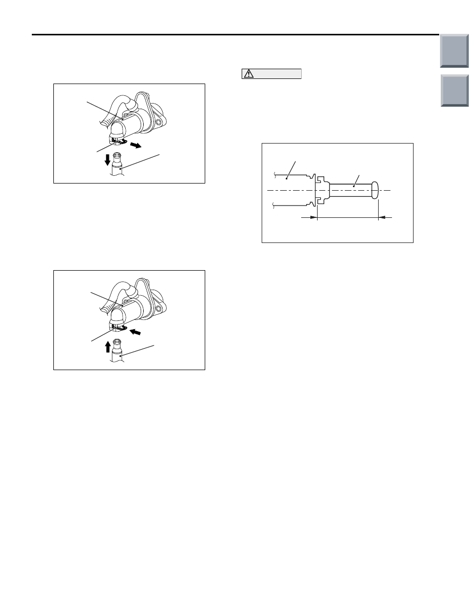
<<A>> CLUTCH PIPE ASSEMBLY A DIS-
CONNECTION
AC311380
AF
Clip
Clutch master
cylinder
Clutch pipe
assembly A
Use a screwdriver to push out the clip, and discon-
nect the clutch hose or clutch pipe assembly A from
the clutch master cylinder.
INSTALLATION SERVICE POINT
>>A<< CLUTCH PIPE ASSEMBLY A CON-
NECTION
AC311380
AG
Clip
Clutch master
cylinder
Clutch pipe
assembly A
Install the clip to the clutch master cylinder, and then
connect the clutch pipe assembly A to the clutch
master cylinder.
>>B<< CLUTCH MONITOR SWITCH
INSTALLATION
CAUTION
Pulling out the plunger section too frequently
may damage the automatic adjustment mecha-
nism section of the clutch monitor switch
because it is made of plastics. If the plunger sec-
tion is pulled out at least 2 or 3 times, replace the
clutch monitor switch.
AC404940
Clutch monitor switch
AD
Approximately 26 mm
Plunger section
1. Pull out the plunger section of the clutch monitor
switch to the maximum length (approx. 26 mm).
NOTE: The clutch monitor switch incorporates the
automatic adjustment mechanism for the plunger
section.
2. Depress the clutch pedal fully and hold it to install
the clutch monitor switch.
NOTE: By installing the clutch monitor switch
while the clutch pedal is depressed, the plunger
section is adjusted to the standard value automat-
ically.
3. Hold the clutch pedal to prevent it from moving,
and press in the clutch monitor switch to the
bracket of the clutch pedal assembly. Then, turn
the clutch monitor switch clockwise to install it.
NOTE: By installing the clutch monitor switch as
described above, the plunger section is adjusted
to the standard value automatically.
4. Connect the clutch monitor switch connector.
Main
Index
Group
TOC