Mitsubishi Colt Ralliart. Manual - part 535
 

  Index      Mitsubishi     Mitsubishi Colt Ralliart - service repair manual


Search            


Content   ..  533  534  535  536   ..


Mitsubishi Colt Ralliart. Manual - part 535


ON-VEHICLE SERVICE

HEATER, AIR CONDITIONER AND VENTILATION

55A-48

ON-VEHICLE SERVICE

COMPRESSOR DRIVE BELT 
ADJUSTMENT

M1552001000487

Refer to GROUP 11A, On-vehicle Service 

− Drive 

Belt Tension Check 

P.11A-6

.

DISCHARGING SYSTEM

M1552013000202

Use the refrigerant recovery unit to discharge refrig-
erant gas front the system.
NOTE: Refer to the Refrigerant Recovery and Recy-
cling Unit instruction Manual for operation of the unit.

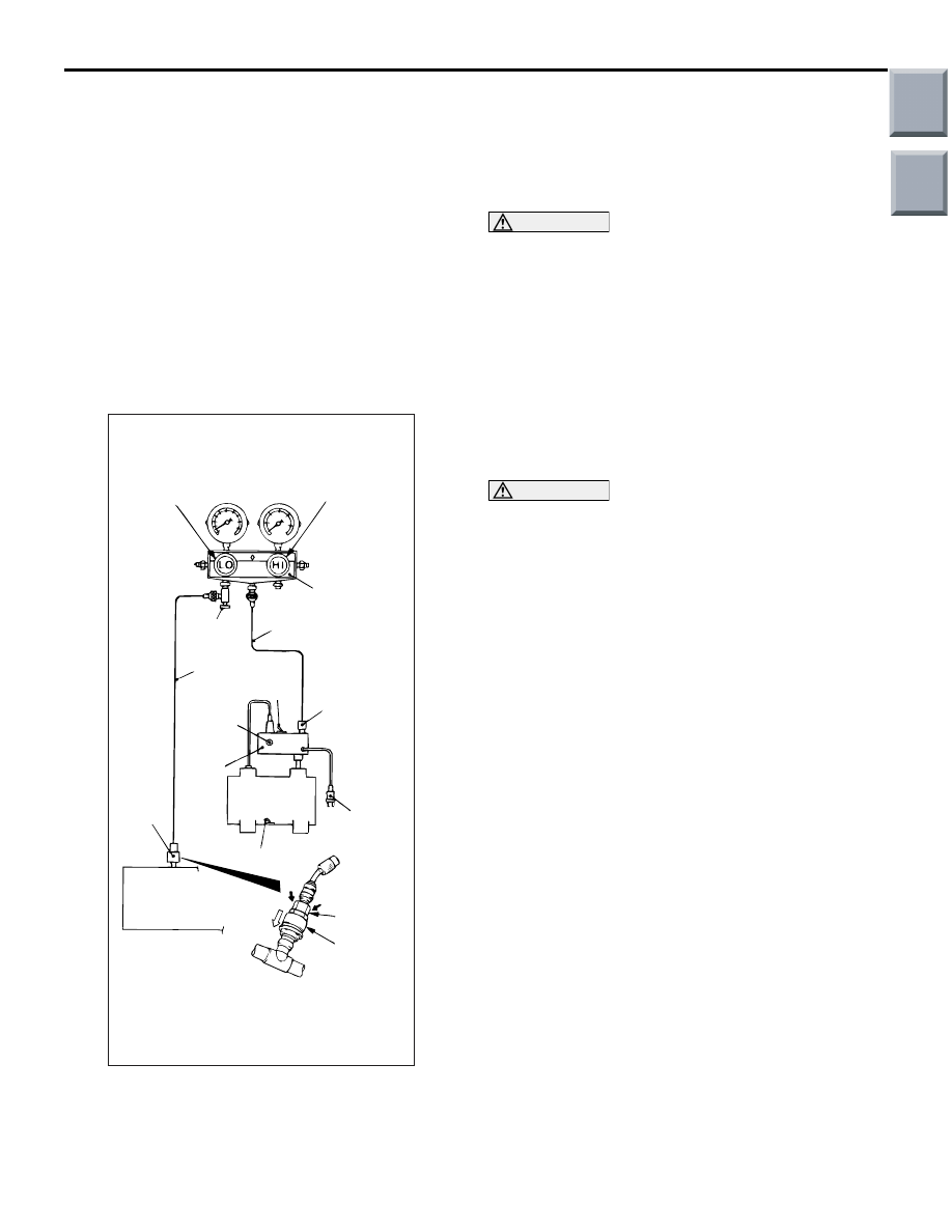
CHARGING

M1552001200511

AC212526AB

A

Sleeve

Low-pressure
service valve

Quick 
joint 
(for low
pressure)

Switch

Vacuum
pump

Power supply
plug

Vacuum 
pump
adaptor

R-12 
connection
port

Charging hose
(blue)

Adapter
valve

Charging hose
(yellow)

Gauge manifold

Switch

R-134a 
connection
port

Low-pressure
valve

High-pressure
valve

1. With the handles turned back all the way (valve 

closed), install the adaptor valve to the 
low-pressure side of the gauge manifold.

2. Connect the charging hose (blue) to the adaptor 

valve.

3. Connect the quick joint (for low-pressure) to the 

charging hose (blue).

CAUTION

• Use tools that are suited to R134a.
• To install the quick joint, press section when 

connecting, run your hand along the hose 
while pressing to ensure that there are no 
bends in the hose.

4. Connect the quick joint (for low-pressure) to the 

low- pressure service valve.
NOTE: The low-pressure service valve should be 
connected to the flexible suction hose.

5. Close the high and low-pressure valves of the 

gauge manifold.

CAUTION

Be sure to connect the power plug of the vacuum 
pump to the vacuum pump adapter, and then 
connect the power plug of the adapter to a 100-V 
outlet.
6. Install the vacuum pump adaptor to the vacuum 

pump.

7. Connect the charging hose (yellow) to the R-134a 

connection port of the vacuum pump adaptor.

8. Tighten the adaptor valve handle (valve open).
9. Open the low-pressure valve of the gauge 

manifold.

10.Turn the power switch of the vacuum pump to the 

ON position.
NOTE: Even if the vacuum pump power switch is 
turned ON, the vacuum pump will not operate 
because of the power supply connection in step 
(6).

Main

Index

Group

TOC

ON-VEHICLE SERVICE

HEATER, AIR CONDITIONER AND VENTILATION

55A-49

CAUTION

Do not operate the compressor for evacuation.

AC212535

Vacuum
pump

Low-pressure
service valve

AB

Vacuum pump 
adaptor switch

11.Turn the vacuum pump adaptor switch to the 

R134a side to start the vacuum pump.

12.Evacuate to a vacuum reading of 100 kPa or 

higher (takes approx. 10 minutes).

CAUTION

Do not operate the compressor in the vacuum 
condition; damage may occur.
13.Loosen the valve of the adapter valve fully (valve 

closed), and turn off the vacuum pump adapter 
switch. Then leave it for five minutes.

14.Check the system for proper sealing (negative 

pressure should not decrease).

AC212536

Valve open

Valve close

Charging valve

Service can

Adaptor valve

AB

15.Connect the service can valve to the service can 

with the handle loosened fully (valve closed).

16.Turn the handle of the adaptor valve back all the 

way (valve closed), remove it from the gauge 
manifold and install the service can.

17.Tighten the handle of the charging valve (valve 

closed) to puncture the service can.

CAUTION

If the service can is inverted, liquid refrigerant 
may be drawn into the compressor damaging it 
by liquid compression. Keep the service can 
upright to ensure that refrigerant is charged in 
gas state.

AC212537

Charging valve

Service can 
(Refrigerant container)

Low-pressure 
service valve

AB

18.Turn the handle of the charging valve back (valve 

open) and tighten the handle of the adaptor valve 
(valve open) to charge the system with refrigerant.

19.If the refrigerant is not drawn in, turn the handle of 

the adaptor valve back all the way (valve closed).

20.Check for gas leaks using a leak detector. If a gas 

leak is detected, re-tighten the connections, and 
then repeat the charging procedure from 
evacuation in step (11).

CAUTION

The leak detector for R-134a should be used.
21.Start the engine.
22.Operate the A/C and set to the lowest 

temperature (MAX. COOL).

23.Fix the engine speed at 1,500 r/min.

Main

Index

Group

TOC

ON-VEHICLE SERVICE

HEATER, AIR CONDITIONER AND VENTILATION

55A-50

CAUTION

If the service can is inverted, liquid refrigerant 
may be drawn into the compressor damaging it 
by liquid compression. Keep the service can 
upright to ensure that refrigerant is charged in 
gas state.
24.Tighten the handle of the adaptor valve (valve 

open) to charge the required volume of 
refrigerant.

25.After charging with refrigerant, turn the handle of 

the adaptor valve back all the way (valve closed).

26.Tighten the charging valve handle (valve closed). 

Remove the quick joint (for low-pressure) from the 
low-pressure service valve.

27.Remove the service can.

NOTE: If the service can is not emptied com-
pletely, keep the handles of the charging valve 
and adaptor valve closed for the next charging.

CHECK THE REFRIGERANT LEVEL

M1552021700057

Remove the refrigerant by the flon reclaim machine 
and replenish the specified quantity of refrigerant.
NOTE: Refer to the Refrigerant Recovery and Recy-
cling Unit instruction Manual for operation of the unit.

PERFORMANCE TEST

M1552001400537

1. The vehicles to be tested should be in a place that 

is not in direct sunlight.

AC001388

Low-pressure
valve

High-pressure
valve

Gauge manifold

Charging
hose (red)

A

Sleeve

Charging
hose (blue)

Adaptor valve
(for low-
pressure)

Low-
pressure
service
valve

High-
pressure
service
valve

AB

Adaptor valve
(for high-
pressure)

2. Close the high and low-pressure valve of the 

gauge manifold.

3. Connect the charging hose (blue) to the 

low-pressure valve and connect the charging 
hose (red) to the high-pressure valve of the gauge 
manifold.

CAUTION

• To connect the quick joint, press section A 

firmly against the service valve until a click is 
heard.

• When connecting, run your hand along the 

hose while pressing to ensure that there are 
no bends in the hose.

4. Install the quick joint (for low-pressure) to the 

charging hose (blue), and connect the quick joint 
(for high-pressure) to the charging hose (red).
NOTE: The high-pressure service valve is on the 
A/C pipe and the low-pressure service valve is on 
the suction hose.

5. Connect the quick joint (for low-pressure) to the 

low-pressure service valve and connect the quick 
joint (for high-pressure) to the high-pressure 
service valve.

6. Start the engine.
7. Set the A/C controls as follows:

• A/C switch: A/C − ON position

• Mode selection: FACE position

• Temperature control: MAXIMUM COOLING posi-

tion

• Air selection: RECIRCULATION position

• Blower switch: Fast position 

8. Adjust engine speed to 1,500 r/min with A/C 

clutch engaged.

9. Engine should be warmed up with doors and 

windows opened.

AC314114

Thermometer

AB

10.Insert a thermometer in the centre air outlet and 

operate the engine for 20 minutes.

NOTE: If the clutch cycles, take the reading before 
the clutch disengages.
11.Note the discharge air temperature.

Main

Index

Group

TOC

ON-VEHICLE SERVICE

HEATER, AIR CONDITIONER AND VENTILATION

55A-51

PERFORMANCE TEMPERATURE CHART

Garage ambient temperature 

°C

20

25

30

35

Discharge air temperature 

°C

3.5 

− 5.5

3.5 

− 5.5

4.5 

− 6.5

5.5 

− 7.5

Compressor high pressure kPa

1, 050 

− 1, 250 1, 050 − 1, 250 1,400 − 1,600

1,650 

− 1,850

Compressor low pressure kPa

120 

− 140

120 

− 140

130 

− 150

160 

− 180

SIMPLE INSPECTION OF THE A/C 
PRESSURE SENSOR

M1552014700226

1. Assemble a gauge manifold on the high pressure 

service valve.

AC207081

2 3

1

AD

AC303045

MB991658

AB

A/C 
pressure 
sensor side

Harness side

2. Disconnect the A/C pressure sensor connector 

and connect the special tool test harness 
(MB991658) as shown.

3. Start the engine and then turn ON the air 

conditioner switch.

AC208297

0

1

2

3

1

2

3

4

5

AB

Output voltage 

(V)

Refrigerant pressure (MPa)

4. At this time, check to see that the voltage of the 

A/C pressure sensor connector terminal No. 2 
reflects the specifications of the figure.
NOTE: The allowance shall be defined as 

±

5%.

REPLACE THE A/C COMPRESSOR 
RELAY

M1552019100069

AC205483

AB

CAUTION

Basically, remove or install the relay by hand. If 
the centre of relay has been pinched by pliers, it 
can be damaged. 

AC205485

AE

Hold this part.

AC205484

1. Remove the relay by hand. If it cannot be 

removed by hand, pinch the relay shown with 
long-nose pliers and remove the relay.

2. Install the new relay by hand.

Main

Index

Group

TOC


Content   ..  533  534  535  536   ..