Mitsubishi Colt Ralliart. Manual - part 457
 

  Index      Mitsubishi     Mitsubishi Colt Ralliart - service repair manual


Search            


Content   ..  455  456  457  458   ..


Mitsubishi Colt Ralliart. Manual - part 457


STEERING SHAFT

POWER STEERING

37-95

DISASSEMBLY SERVICE POINT
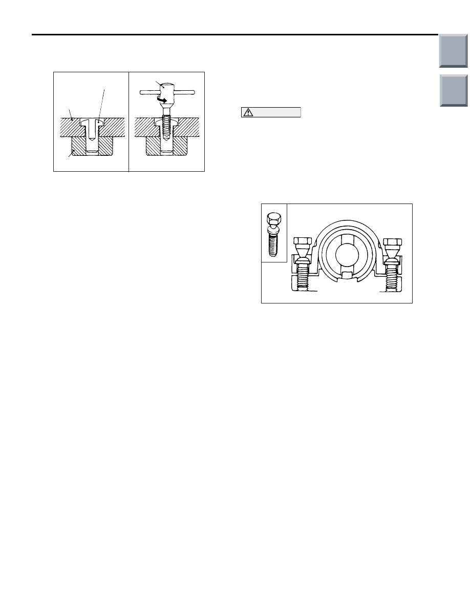
<<A>> SPECIAL BOLT REMOVAL

ACX01138 AB

Steering lock 
bracket

Reverse screw tap

Special bolt

Steering lock 
cylinder

1. Drill in the special bolt a hole deep enough for the 

tap to stand.

2. Remove the special bolt with a left-hand tap.

REASSEMBLY SERVICE POINT
>>A<< ENGINE STARTING SWITCH 
ASSEMBLY/ENGINE STARTING SWITCH 
BRACKET/SPECIAL BOLT INSTALLA-
TION

CAUTION

The engine starting switch bracket and bolts 
must be replaced with new ones when the engine 
starting switch is installed.
1. When installing the engine starting switch 

assembly and engine starting switch bracket to 
the steering column assembly, temporarily install 
the engine starting switch in alignment with the 
column boss.

ACX01139 AB

2. After checking that the lock works properly, 

tighten the special bolts until the head twists off.

Main

Index

Group

TOC

POWER STEERING GEAR BOX AND LINKAGE

POWER STEERING

37-96

POWER STEERING GEAR BOX AND LINKAGE

REMOVAL AND INSTALLATION

M1372010900828

WARNING

Before removing the steering gear, refer to GROUP 52B, Service Precautions (

P.52B-5

) and 

Driver’s, Front Passenger’s Air Bag Module(s) and Clock Spring (

P.52B-145

). Position the 

front wheels in a straight-ahead direction. Failure to do so may damage the SRS clock spring 
and render the SRS system inoperative, risking serious injury.

Operations before Steering Gear and Linkage Assembly 
Removal
• Front Under Cover Panel Removal (Refer to GROUP 51, 

Front Bumper Assembly and Radiator Grille 

P.51-2

 ).

• Lower Arm Removal (Refer to GROUP 33, Lower Arm 

P.33-11

 <4A9>, 

P.33-13

 <4G1>).

• Exhaust Front Pipe Removal (Refer to GROUP 15, 

Exhaust Pipe and Main Muffler 

P.15-19

 <4A9>, 

P.15-21


<4G1>).

• Engine Roll Stopper Rod Assembly Removal (Refer to 

GROUP 32, Engine Roll Stopper Rod 

P.32-11

).

• Air Bag Module and Steering Wheel Assembly Removal 

(Refer to 

P.37-90

).

• Clock Spring Removal (Refer to GROUP 52B, Driver’s, 

Front Passenger’s Air Bag Module(s) and Clock Spring 

P.52B-145

).

• Electric Power Steering Control Unit Bracket Removal 

(Refer to 

P.37-102

).

Operations after Tie-rod End Assembly Installation
• Push the tie-rod end cover with fingers and inspect for 

cracks or damage.

• Wheel Alignment Check and Adjustment (Refer to 

GROUP 33, On-vehicle Service 

− Front Wheel Alignment 

Check and Adjustment 

P.33-5

).

Operations after Steering Gear and Linkage Assembly 
Installation
• Push the tie-rod end cover with fingers and inspect for 

cracks or damage.

• Electric Power Steering Control Unit Bracket Installation 

(Refer to 

P.37-102

).

• Confirm that the steering wheel is at the straight-ahead 

position.

• Clock Spring Installation (Refer to GROUP 52B, Driver’s, 

Front Passenger’s Air Bag Module(s) and Clock Spring 

P.52B-145

).

• Steering Wheel Assembly and Air Bag Module Installation 

(Refer to 

P.37-90

).

• Engine Roll Stopper Rod Assembly Installation (Refer to 

GROUP 32, Engine Roll Stopper Rod 

P.32-11

).

• Exhaust Front Pipe Installation (Refer to GROUP 15, 

Exhaust Pipe and Main Muffler 

P.15-19

 <4A9>, 

P.15-21


<4G1>).

• Lower Arm Installation (Refer to GROUP 33, Lower Arm 

P.33-11

 <4A9>, 

P.33-13

 <4G1>).

• Wheel Alignment Check and Adjustment (Refer to 

GROUP 33, On-vehicle Service 

− Front Wheel Alignment 

Check and Adjustment 

P.33-5

).

• Front Under Cover Panel Installation (Refer to GROUP 

51, Front Bumper Assembly and Radiator Grille 

P.51-2

).

Main

Index

Group

TOC

AC601478

2

4

3

11

8

6

5

12

25 ± 5 N·m

80 ± 10 N·m

9.0 ± 2.0 N·m

18 ± 2 N·m

N

AB

7

80 ± 10 N·m

12

13

14

43 ± 7 N·m

10

<4A9 (A/T)>

1

: Instant adhesive (Three Bond 1741 or equivalent)

AC600196

2

4

3

11

8

6

5

12

9.0 ± 2.0 N·m

18 ± 2 N·m

N

AC

7

58 ± 6 N·m

12

: Instant adhesive (Three Bond 1741 or Equivalent)

13

14

43 ± 7 N·m

10

9

1

<4A9 (M/T) and 4G1>

58 ± 6 N·m

28 ± 3 N·m <4G1>

25 ± 5 N·m <4A9 (M/T)>

Tie-rod end assembly removal 
steps 

1.

self-locking nut

<<

A

>>

2.

Tie-rod end and knuckle connection

14. Tie-rod end assembly

POWER STEERING GEAR BOX AND LINKAGE

POWER STEERING

37-97

Tie-rod end assembly removal 
steps (Continued)

Main

Index

Group

TOC

Steering gear and linkage 
assembly removal steps 

1.

self-locking nut

<<

A

>>

2.

Tie-rod end and knuckle connection

<<

B

>>

>>

G

<< 3.

Steering gear and steering column 
assembly connection

>>

F

<<

4.

Steering gear connector (in-vehicle 
EPS-ECU)

>>

E

<<

5.

Steering gear bolt (earth bolt)

<<

C

>>

>>

D

<<

6.

Front axle No.1 crossmember 
(Equipped with steering gear and 
linkage assembly, steering column 
dash panel cover, and stabilizer 
bar)

7.

Steering gear mounting 
crossmember plate 

8.

Steering gear mounting rod side 
bracket

9.

Steering gear mounting bracket 
<4A9 (M/T) and 4G1>

>>

C

<<

10. Steering gear and linkage assembly

>>

B

<<

11. Steering column dash panel cover
12. Steering gear bushing

>>

A

<<

13. Steering gear cushion

POWER STEERING GEAR BOX AND LINKAGE

POWER STEERING

37-98

REMOVAL SERVICE POINTS
<<A>> TIE-ROD END AND KNUCKLE DIS-
CONNECTION

CAUTION

• Do not remove the nut from ball joint. Loosen 

it and use the special tool to avoid possible 
damage to ball joint threads.

• Hang the special tool with cord to prevent it 

from falling. 

<4A9>

AC208247AJ

Cord

Bolt

MB991897
or
MB992011

Nut

Ball joint

1. Install special tool ball joint remover (MB991897 

or MB992011) as shown in the figure.

AC106821

Knob

Parallel

Bolt

Correct

Wrong

AD

2. Turn the bolt and knob as necessary to make the 

jaws of special tool  parallel, tighten the bolt by 
hand and confirm that the jaws are still parallel.
NOTE: When adjusting the jaws in parallel, make 
sure the knob is in the position shown in the fig-
ure.

3. Tighten the bolt with a wrench to disconnect the 

tie rod end, lower arm ball joint.

<4G1>

AC102599AC

Cord

Bolt

MB991113

Nut

Ball joint

Replace the self-locking nut with a regular nut, and 
then install special tool steering linkage puller 
(MB991113) as shown in the figure.

Steering gear and linkage 
assembly removal steps 

Main

Index

Group

TOC


Content   ..  455  456  457  458   ..