Mitsubishi Colt Ralliart. Manual - part 452
TROUBLESHOOTING
POWER STEERING
37-75
DIAGNOSIS PROCEDURE
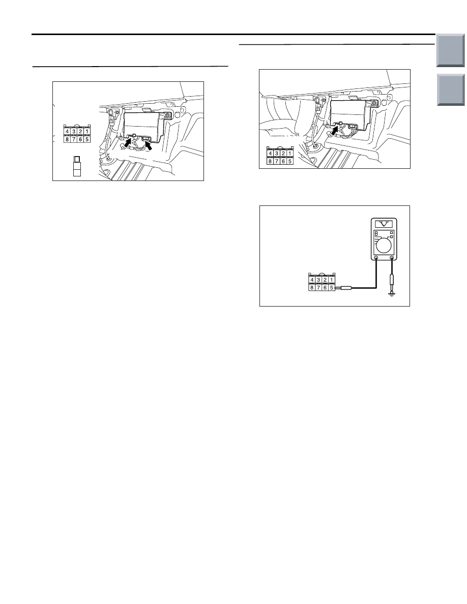
STEP 1. Check the connectors and terminals.
•
AC314189AE
Connector: B-37, B-38
B-37
B-38
Harness side
B-37
21
22
B-38
Electric power steering-ECU connectors B-37 and
B-38
Check the connectors above for improper engage-
ment, terminal damage or terminal drawn in the con-
nector case.
Q: Are the connectors and terminals in good
condition?
YES :
Go to Step 2.
NO :
Repair the connector(s) or terminal(s).
STEP 2. Voltage measurement at electric power
steering-ECU connector B-37.
•
AC314189AF
Connector: B-37
Harness side
Disconnect the connector, and measure at the wiring
harness side.
• Ignition Switch: ON
•
AC313972 BW
Harness side
B-37
Measure the voltage between electric power steer-
ing-ECU connector B-37 terminal No.5 and body
earth
OK: system voltage
Q: Is the check result normal?
YES :
Go to Step 3.
NO :
Go to Step 5.
Main
Index
Group
TOC