Mitsubishi Colt Ralliart. Manual - part 431
INPUT SIGNAL PROCEDURES
SMART WIRING SYSTEM (SWS) USING SWS MONITOR
54C-232
DIAGNOSIS PROCEDURE
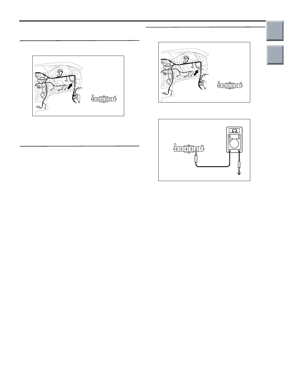
Step 1. Connector check: B-19 fog lamp switch
connector
Q: Is the check result normal?
YES :
Go to Step 2.
NO :
Repair the defective connector.
Step 2. Check the front fog lamp switch.
Refer to GROUP 54A
− Fog lamp
Q: Is the check result normal?
YES :
Go to Step 3.
NO :
Replace the fog lamp switch.
Step 3. Resistance measurement at the B-19 fog
lamp switch connector.
(1) Remove the fog lamp switch, and measure at the
wiring harness side.
(2) Resistance between B-19 fog lamp switch
connector terminal No.2 and body earth
OK: Continuity exists (2
Ω or less)
Q: Is the check result normal?
YES :
Go to Step 5.
NO :
Go to Step 4.
AC401055
Connector: B-19
AK
Harness side
AC401055
Connector: B-19
AK
Harness side
AC310506 DT
Connector B-19
(Harness side)
Main
Index
Group
TOC