Mitsubishi Colt Ralliart. Manual - part 414
 

  Index      Mitsubishi     Mitsubishi Colt Ralliart - service repair manual


Search            


Content   ..  412  413  414  415   ..


Mitsubishi Colt Ralliart. Manual - part 414


SYMPTOM PROCEDURES

SMART WIRING SYSTEM (SWS) USING SWS MONITOR

54C-164

Step 10. Check the wiring harness between B-115 
fog lamp relay connector terminal No.2 to B-133 
ETACS-ECU connector terminal No.67.

NOTE: Prior to the wiring harness inspection, check 
junction block connector B-131, and repair if neces-
sary.

• Check the output lines for open circuit.

Q: Is the check result normal?

YES : 

Go to Step 11.

NO : 

Repair the wiring harness.

Step 11. Retest the system.
Check that the fog lamps illuminate normally.

Q: Is the check result normal?

YES : 

The trouble can be an intermittent 

malfunction (Refer to GROUP 00 

− How to 

use Troubleshooting/inspection Service 
Points 

− How to Cope with Intermittent 

Malfunction 

P.00-13

).

NO : 

Replace the ETACS-ECU.

AC313824 AH

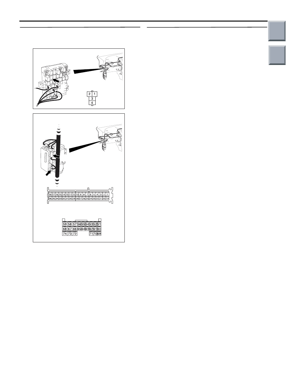
Connector: B-115

Junction block side

Junction block (Front view)

AC313827AF

B-131

B-131

B-133 (GR)

B-133

Connectors: B-131, B-133

Junction block (Rear view)

Harness side

Harness side

Main

Index

Group

TOC

SYMPTOM PROCEDURES

SMART WIRING SYSTEM (SWS) USING SWS MONITOR

54C-165

INSPECTION PROCEDURE K-2: Any of the fog lamps does not illuminate.

CAUTION

Whenever the ECU is replaced, ensure that the 
input and output signal circuits are normal.

COMMENTS ON TROUBLE SYMPTOM

If any of the fog lamps do not illuminate, the wiring 
harness connector(s), the bulb or the fuse may be 
defective or burned out.

POSSIBLE CAUSES

• Burned-out fog lamp bulb

• Damaged harness wires and connectors

FOG LAMP
RELAY

FOG LAMP
(RH)

FOG LAMP
(LH)

Fog Lamps Circuit

Wire colour code
B : Black     LG : Light green     G : Green     L : Blue     W : White     Y : Yellow     SB : Sky blue
BR : Brown     O : Orange     GR : Grey     R : Red     P : Pink     V : Violet     PU : Purple

Main

Index

Group

TOC

SYMPTOM PROCEDURES

SMART WIRING SYSTEM (SWS) USING SWS MONITOR

54C-166

DIAGNOSIS PROCEDURE

Step 1. Connector check: A-22 fog lamp (RH) 
connector or A-15 fog lamp (LH) connector

Q: Is the check result normal?

YES : 

Go to Step 2.

NO : 

Repair the defective connector.

Step 2. Check the bulbs of the fog lamps lamp.
Check the bulb(s) of the defective lamp.

Q: Is the check result normal?

YES : 

Go to Step 3.

NO : 

Replace the bulb(s) of the defective lamp.

Step 3. Resistance measurement at the A-22 fog 
lamp (RH) connector or A-15 fog lamp (LH) 
connector.

(1) Disconnect the connector, and measure at the 

wiring harness side.

(2) Check the resistance between the lamp 

connector and body earth.

Resistance between A-22 fog lamp (RH) connec-

tor terminal No.1 and body earth

• Resistance between A-15 fog lamp (LH) con-

nector terminal No.1 and body earth

OK: Continuity exists (2 

 or less)

Q: Is the check result normal?

YES : 

Go to Step 5.

NO : 

Go to Step 4.

AC509191

Connector: A-15

AC

A-15 (B)

Harness side

AC509176

Connector: A-22

AD

A-22 (GR)

Harness side

AC509191

Connector: A-15

AC

A-15 (B)

Harness side

AC509176

Connector: A-22

AD

A-22 (GR)

Harness side

AC310506EB

Connector: A-15, A-22 
(Harness side)

Main

Index

Group

TOC

SYMPTOM PROCEDURES

SMART WIRING SYSTEM (SWS) USING SWS MONITOR

54C-167

Step 4. Check the wiring harness from A-22 fog 
lamp (RH) connector or A-15 fog lamp (LH) 
connector terminal No.1 to body earth.

• Check the earth wires for open circuit.

Q: Is the check result normal?

YES : 

Go to Step 7.

NO : 

Repair the wiring harness.

Step 5. Connector check: Connector check: 
B-115 fog lamp relay connector

Q: Is the check result normal?

YES : 

Go to Step 6.

NO : 

Repair the defective connector.

Step 6. Check the wiring harness from A-22 fog 
lamp (RH) connector or A-15 fog lamp (LH) 
connector terminal No.2 to B-115 fog lamp relay 
connector terminal No.4.

NOTE: Prior to the wiring harness inspection, check 
junction block connector B-112, and repair if neces-
sary.

• Check the power supply line for open circuit.

AC509191

Connector: A-15

AC

A-15 (B)

Harness side

AC509176

Connector: A-22

AD

A-22 (GR)

Harness side

AC313824 AH

Connector: B-115

Junction block side

Junction block (Front view)

AC509191

Connector: A-15

AC

A-15 (B)

Harness side

AC509176

Connector: A-22

AD

A-22 (GR)

Harness side

AC313825

Connectors: B-112, B-115

AH

B-115

B-112

B-112

B-115

Junction block (Front view)

Harness side

Junction block side

Main

Index

Group

TOC


Content   ..  412  413  414  415   ..