Mitsubishi Colt Ralliart. Manual - part 381


  Index      Mitsubishi     Mitsubishi Colt Ralliart - service repair manual


Search            


Content   ..  379  380  381  382   ..


Mitsubishi Colt Ralliart. Manual - part 381


CHECK TROUBLE BY USING THE INPUT SIGNAL CHECK

SMART WIRING SYSTEM (SWS) USING SWS MONITOR

54C-32

CHECK TROUBLE BY USING THE INPUT SIGNAL CHECK

M1549024200608

<Data list, function diagnosis or pulse check>
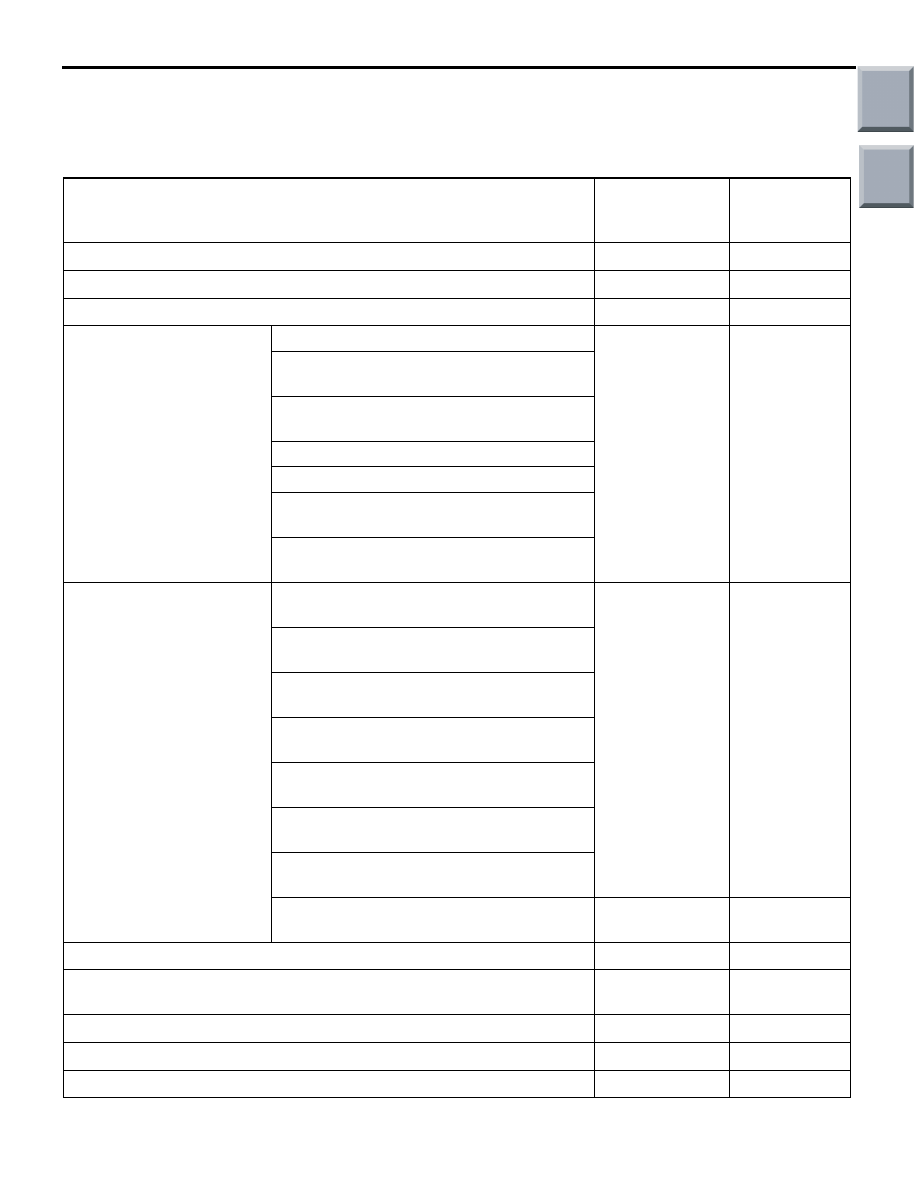
If a problem is found in the Service Data or Pulse Check inspection, observe the table below.

Symptom

Inspection 
procedure 
number

Reference 
page

The ignition switch (ACC) signal is not received.

N-1

P.54C-201

The ignition switch (IG1) signal is not received.

N-2

P.54C-203

The driver's door switch signal is not received.

N-3

P.54C-205

Column switch (lighting 
and turn-signal lamp 
switch)

The tail lamp switch signal is not received. N-4

P.54C-208

The headlamp switch signal is not 
received.
The auto lamp switch signal is not 
received.
The dimmer switch signal is not received.
The passing switch signal is not received.
The turn-signal lamp switch (LH) signal is 
not received.
The turn-signal lamp switch (RH) signal is 
not received.

Column switch (windshield 
wiper/washer and rear 
wiper/washer switch)

The windshield mist wiper switch signal is 
not received.

N-5

P.54C-210

The windshield intermittent wiper switch 
signal is not received.
The windshield low-speed wiper switch 
signal is not received.
The windshield high-speed wiper switch 
signal is not received.
The windshield washer switch signal is not 
received.
The rear wiper switch signal is not 
received.
The rear washer switch signal is not 
received.
The windshield intermittent wiper volume 
signal is not received.

N-6

P.54C-211

The key reminder switch signal is not received.

N-7

P.54C-213

Signal is not received from the remote controlled mirror switch 
(folding/unfolding switch).

N-8

P.54C-216

The hazard warning lamp switch signal is not received.

N-9

P.54C-219

All the door switch signals are not received.

N-10

P.54C-222

The driver's door lock actuator switch signal is not received.

N-11

P.54C-226

Main

Index

Group

TOC

OPERATION AND FUNCTION QUICK-REFERENCE TABLE FOR INPUT SIGNAL INSPECTION PROCEDURES

SMART WIRING SYSTEM (SWS) USING SWS MONITOR

54C-33

OPERATION AND FUNCTION QUICK-REFERENCE TABLE 

FOR INPUT SIGNAL INSPECTION PROCEDURES

M1549020300517

If troubles have occurred in the functions which use the SWS simultaneously, observe the table below to 
check input signals.
(This table shows only the input signals which will cause troubles in at least two functions simultaneously).

Each switch signal of the keyless entry transmitter is not received.

N-12

P.54C-229

The fog lamp switch signal is not received.

N-13

P.54C-231

The passenger's door switch signal is not received.

N-14

P.54C-234

Symptom

Inspection 
procedure 
number

Reference 
page

Function

N-1

N-2

N-3

N-4

N-5

N-7

N-10 N-11 N-12

Lamp reminder buzzer function

×

×

×

Door-ajar buzzer function

×

Turn-signal lamp operation sound function

×

Central door lock control

×

Keyless entry system

×

×

×

×

Keyless entry hazard answerback function

×

×

Multi-mode keyless entry

×

Power window timer function

×

×

Control of windshield wiper washer

×

×

Rear wiper washer control

×

×

Control of electric folding remote-controlled 
mirror

×

Ignition key cylinder illumination lamp function −

×

×

×

Headlamp control

×

Tail lamp control

×

Fog lamp control

×

Turn-signal lamp control

×

×

Room lamp control

×

×

×

×

Door-ajar indicator lamp

×

×

Main

Index

Group

TOC

SYMPTOM PROCEDURES

SMART WIRING SYSTEM (SWS) USING SWS MONITOR

54C-34

SYMPTOM PROCEDURES

INSPECTION PROCEDURE A-1: Communication with the SWS monitor is not possible.

CAUTION

Whenever the ECU is replaced, ensure that the 
input and output signal circuits are normal.

COMMENTS ON TROUBLE SYMPTOM

The SWS monitor may be connected improperly.

POSSIBLE CAUSES

• Malfunction of the SWS monitor body (I/F car-

tridge)

• Malfunction of the SWS monitor harness

• Malfunction of the ETACS-ECU

• Damaged harness wires and connectors

DIAGNOSIS PROCEDURE

Step 1. Check that the M.U.T.-III communicates 
with the other systems.
Check whether the M.U.T.-III can communicate with 
the other systems.

Q: Is the check result normal?

YES : 

Go to Step 2.

NO : 

Diagnose the system, which cannot 
communicate with the M.U.T.-III.

Step 2. Check that the M.U.T.-III can communicate 
with the system.
When the ignition switch is turned ON, check if the 
M.U.T.-III can communicate with the system.

Q: Is the check result normal?

YES : 

Refer to Inspection Procedure A-3 

"Communication with the ETACS-ECU is 
not possible 

P.54C-41

."

NO : 

Go to Step 3.

Step 3. Connector check: B-134 ETACS-ECU 
connector

Q: Is the check result normal?

YES : 

Go to Step 4.

NO : 

Repair the defective connector.

AC313826

Connector: B-134

AG

Junction block side

Junction block (Rear view)

Main

Index

Group

TOC

SYMPTOM PROCEDURES

SMART WIRING SYSTEM (SWS) USING SWS MONITOR

54C-35

Step 4. Resistance measurement at the B-134 
ETACS-ECU connector.

(1) Disconnect the connector, and measure at the 

junction block side.

(2) Resistance between B-134 ETACS-ECU 

connector terminal No.2 and body earth.

OK: Continuity exists (2 

 or less)

Q: Is the check result normal?

YES : 

Go to Step 6.

NO : 

Go to Step 5.

Step 5. Check the wiring harness between B-134 
ETACS-ECU connector terminal No.2 to body 
earth.

NOTE: Prior to the wiring harness inspection, check 
junction block connectors B-130, and repair if neces-
sary.

• Check the earth wires for open circuit.

Q: Is the check result normal?

YES : 

The trouble can be an intermittent 

malfunction (Refer to GROUP 00 

− How to 

use Troubleshooting/inspection Service 
Points 

− How to Cope with Intermittent 

Malfunction 

P.00-13

).

NO : 

Repair the wiring harness.

AC313826

Connector: B-134

AG

Junction block side

Junction block (Rear view)

AC310506DW

Connector B-134
(Junction block side)

AC313827

Connectors: B-130, B-134

AD

Junction block side

Junction block (Rear view)

B-134

B-130

B-134

Harness side

B-130

Main

Index

Group

TOC


Content   ..  379  380  381  382   ..