Mitsubishi Colt Ralliart. Manual - part 377
 

  Index      Mitsubishi     Mitsubishi Colt Ralliart - service repair manual


Search            


Content   ..  375  376  377  378   ..


Mitsubishi Colt Ralliart. Manual - part 377


DIAGNOSIS TROUBLE CODE PROCEDURES

SMART WIRING SYSTEM (SWS) USING SWS MONITOR

54C-16

DIAGNOSIS TROUBLE CODE PROCEDURES

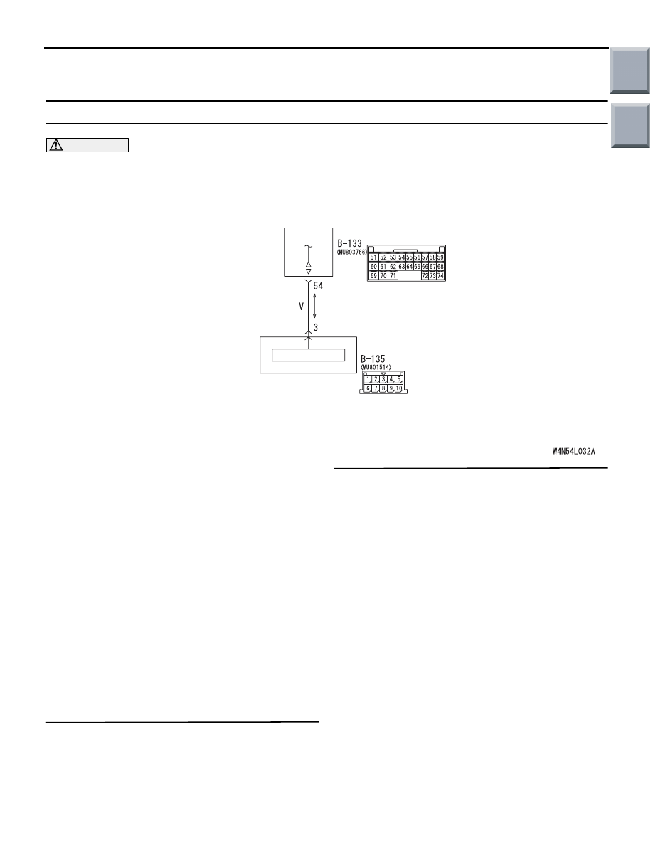
Diagnosis code No.U1700: Trouble in SWS communication line system

CAUTION

If diagnosis code No.u1700 is set in the 
ETACS-ECU, diagnose the CAN bus lines.

TROUBLE JUDGMENT

The ETACS-ECU communicates with the column 
switch through the SWS communication line. If there 
is any trouble in the ETACS-ECU or the SWS com-
munication lines, diagnosis code No.U1700 will be 
set.

COMMENT ON TROUBLE SYMPTOM

The wiring harness wire or connectors may have 
loose, corroded, or damage terminals, or terminals 
pushed back in the connector, or the ETACS-ECU 
may be defective.

POSSIBLE CAUSES

• Malfunction of the ETACS-ECU

• Damaged harness wires and connectors

DIAGNOSIS PROCEDURE

Step 1. M.U.T.-III CAN bus diagnostics
Use the M.U.T.-III to diagnose the CAN bus lines.

Q: Is the check result normal?

YES : . 

Go to Step 2.

NO : . 

Repair the CAN bus line (Refer to GROUP 

54D 

− Diagnosis 

P.54D-13

).

Step 2. Check whether the diagnosis code is 
reset.
Check again if the diagnosis code is set.
(1) Erase the diagnosis code.
(2) Ignition switch: LOCK (OFF) position to ON
(3) On completion, check that the diagnosis code is 

not reset.

Q: Is the check result normal?

YES : 

If a trouble is solved, it is determined that 

there is an intermittent malfunction such as 
poor engaged connector(s) or open circuit 
(Refer to GROUP 00 

− How to use 

Troubleshooting/inspection Service Points 

− 

How to Cope with Intermittent Malfunction 

P.00-13

).

NO : 

Go to Step 3.

ETACS-ECU

COLUMN
SWITCH

COLUMN-ECU

Wire colour code
B : Black     LG : Light green     G : Green     L : Blue     W : White     Y : Yellow     SB : Sky blue
BR : Brown     O : Orange     GR : Gray     R : Red     P : Pink     V : Violet

SWS Communication Line

Main

Index

Group

TOC

DIAGNOSIS TROUBLE CODE PROCEDURES

SMART WIRING SYSTEM (SWS) USING SWS MONITOR

54C-17

Step 3. ECU check by using the SWS monitor
Check that the SWS communication lines are in 
good condition.

• Ignition switch: OFF

ECU TO BE CHECKED

• COLUMN ECU

• ETACS ECU

OK: "OK" are displayed for all the items

Q: Are the check results normal?

Normal conditions are displayed for all the items. : 

The trouble can be an intermittent 
malfunction (Refer to GROUP 00 

− How to 

use Troubleshooting/inspection Service 
Points 

− How to Cope with Intermittent 

Malfunction 

P.00-13

).

"NG" is displayed on the "COLUMN ECU" menu. : 

Refer to Inspection Procedure A-2 
"Communication with the column switch 
(column-ECU) is not possible 

P.54C-37

."

"NG" is displayed on the "ETACS ECU" menu. : 

Refer to Inspection Procedure A-3 
"Communication with the ETACS-ECU is 
not possible 

P.54C-41

."

Diagnosis code No.U1701 Communication error with column switch

CAUTION

If diagnosis code No.U1701 is set in the 
ETACS-ECU, diagnose the CAN bus lines.

TROUBLE JUDGMENT

The ETACS-ECU communicates with the column 
switch through the SWS communication lines. If 
there is any trouble in that communication, diagnosis 
code No.U1701 will be set.

COMMENT ON TROUBLE SYMPTOM

The column switch, the ETACS-ECU, connector(s), 
or wiring harness between the two may be defective.

POSSIBLE CAUSES

• Malfunction of the column switch

• Malfunction of the ETACS-ECU

• Damaged harness wires and connectors

DIAGNOSIS PROCEDURE

Step 1. M.U.T.-III CAN bus diagnostics
Use the M.U.T.-III to diagnose the CAN bus lines.

Q: Is the check result normal?

YES : 

Go to Step 2.

NO : 

Repair the CAN bus line (Refer to GROUP 
54D 

− Diagnosis 

P.54D-13

).

Step 2.Check whether the diagnosis code is 
reset.
Check again if the diagnosis code is set.
(1) Erase the diagnosis code.
(2) Ignition switch: LOCK (OFF) position to ON
(3) On completion, check that the diagnosis code is 

not reset.

Q: Is the check result normal?

YES : 

If a trouble is solved, it is determined that 

there is an intermittent malfunction such as 
poor engaged connector(s) or open circuit 
(Refer to GROUP 00 

− How to use 

Troubleshooting/inspection Service Points 

− 

How to Cope with Intermittent Malfunction 

P.00-13

).

NO : 

Go to Step 3.

Main

Index

Group

TOC

DIAGNOSIS TROUBLE CODE PROCEDURES

SMART WIRING SYSTEM (SWS) USING SWS MONITOR

54C-18

Step 3. ECU check by using the SWS monitor
Check that the power supply and earth lines to the 
ETACS-ECU and the column switch (column-ECU) 
and the SWS communication lines are normal.

• Ignition switch: OFF

ECU TO BE CHECKED

• COLUMN ECU

• ETACS ECU

OK: "OK" is displayed for all the items

Q: Are the check results normal?

Normal conditions are displayed for all the items. : 

The trouble can be an intermittent 
malfunction (Refer to GROUP 00 

− How to 

use Troubleshooting/inspection Service 
Points 

− How to Cope with Intermittent 

Malfunction 

P.00-13

).

"NG" is displayed on the "COLUMN ECU" menu. : 

Refer to Inspection Procedure A-2 
"Communication with the column switch 
(column-ECU) is not possible 

P.54C-37

."

"NG" is displayed on the "ETACS ECU" menu. : 

Refer to Inspection Procedure A-3 
"Communication with the ETACS-ECU is 
not possible 

P.54C-41

."

Diagnosis code No.U1073: Bus off

CAUTION

If diagnosis code No.U1073 is set in the 
ETACS-ECU, diagnose the CAN bus lines.

CAUTION

Whenever the ECU is replaced, ensure that the 
input and output signal circuits are normal.

TROUBLE JUDGMENT

Diagnosis code No.U1073 will be stored when the 
ETACS-ECU ceases CAN communication (bus off) 
and then resumes the communication by turning the 
ignition switch to the "LOCK" (OFF) position.

COMMENTS ON TROUBLE SYMPTOM

The wiring harness wire or connectors may have 
loose, corroded, or damage terminals, or terminals 
pushed back in the connector, or the SWS communi-
cation lines may be defective.

POSSIBLE CAUSES

Damaged harness wires and connectors

DIAGNOSIS PROCEDURE

Step 1. M.U.T.-III CAN bus diagnostics
Use the M.U.T.-III to diagnose the CAN bus lines.

Q: Is the check result normal?

YES : 

Go to Step 2.

NO : 

Repair the CAN bus line (Refer to GROUP 
54D 

− Diagnosis 

P.54D-13

). On completion, 

go to Step 3.

Step 2. Check whether the diagnosis code is 
reset.
Check again if the diagnosis code is set.
(1) Erase the diagnosis code.
(2) Ignition: LOCK (OFF) position to ON
(3) On completion, check that the diagnosis code is 

not reset.

Q: Is the check result normal?

YES : 

The trouble can be an intermittent 

malfunction (Refer to GROUP 00 

− How to 

use Troubleshooting/inspection Service 
Points 

− How to Cope with Intermittent 

Malfunction 

P.00-13

).

NO : 

Go to Step 3.

Step 3. ECU check by using the SWS monitor
Check that the SWS communication lines are in 
good condition.

• Ignition switch: ON

ECU TO BE CHECKED

• ETACS ECU

OK: "OK" is displayed on the "ETACS ECU" 
menu

Q: Is the check result normal?

YES : 

Replace the ETACS-ECU.

NO : 

Refer to Inspection Procedure A-3 
"Communication with the ETACS-ECU is 
not possible 

P.54C-41

."

Main

Index

Group

TOC

DIAGNOSIS TROUBLE CODE PROCEDURES

SMART WIRING SYSTEM (SWS) USING SWS MONITOR

54C-19

Diagnosis code No.U1100: Engine-ECU <M/T> or Engine-CVT-ECU <CVT> time-out (related to engine)


Diagnosis code No.U1101: Engine-CVT-ECU time-out (related to CVT) <CVT>

CAUTION

• If diagnosis code No.U1100 or No.U1101 are 

set in the ETACS, diagnose the CAN main bus 
line.

• Whenever the ECU is replaced, ensure that 

the communication circuit is normal.

TROUBLE JUDGMENT

Diagnosis Code No.U1100

• The ETACS-ECU receives engine and transmis-

sion control signals from the engine-ECU <M/T> 
or engine-CVT-ECU <CVT> through the CAN bus 
lines. If the ECU can not receive the engine con-
trol system-related signal at all, diagnosis code 
No.U1100 will be set.

Diagnosis Code No.U1101

• The ETACS-ECU receives engine and transmis-

sion control signals from the engine-CVT-ECU 
through the CAN bus lines. If the ECU can not 
receive the transmission control system-related 
signal at all, diagnosis code No.U1101 will be set.

COMMENTS ON TROUBLE SYMPTOM

Current trouble

• Connector(s) or wiring harness in the CAN bus 

lines between the ETACS-ECU and the 
engine-ECU <M/T> or engine-CVT-ECU <CVT>, 
the power supply circuits to these ECUs, or the 
ETACS-ECU itself may be defective.

Past trouble

• If diagnosis code No.U1100 and No.U1101 are 

set as past trouble, carry out diagnosis with par-
ticular emphasis on wiring and connector(s) in 
the CAN bus lines between the ETACS-ECU and 
the engine-ECU <M/T> or engine-CVT-ECU 
<CVT>, or power supply to the engine-ECU 
<M/T> or engine-CVT-ECU <CVT>. For diagno-
sis procedures, refer to "How to treat past trou-
ble" (refer to GROUP 00, How to Use 
Troubleshooting/Inspection Service Points 

− How 

to Treat Past Trouble 

P.00-13

).

NOTE: For a past trouble, you can not find it by the 

M.U.T.-III CAN bus diagnostics even if there is 
any failure in CAN bus lines. In this case, refer to 
GROUP 00, How to Use Troubleshooting/Inspec-
tion Service Points 

 How to Cope with Intermit-

tent Malfunctions 

P.00-13

 and check the CAN 

bus lines. You can narrow down the possible 
cause of the trouble by referring to the diagnosis 
code, which is set regarding the CAN communi-
cation-linked ECUs (Refer to GROUP 54D 

 CAN 

Bus Line Diagnosis Flow 

P.54D-7

).

PROBABLE CAUSES

• Malfunction of the engine-ECU <M/T>

• Malfunction of the engine-CVT-ECU <CVT>

• Malfunction of the ETACS-ECU

• Malfunction of the CAN bus

DIAGNOSIS PROCEDURE

Step 1. M.U.T.-III CAN bus diagnostics
Use the M.U.T.-III to diagnose the CAN bus lines.

Q: Is the check result normal?

YES : 

Go to Step 2.

NO : 

Repair the CAN bus line (Refer to GROUP 
54D 

− Diagnosis 

P.54D-13

). Repair the 

CAN bus line.

Step 2. M.U.T.-III other system diagnosis code
Check whether the engine-ECU <M/T> or 
engine-CVT-ECU <CVT> sets a diagnosis code.

Q: Is the check result normal?

YES : 

Diagnose the engine or the CVT (Refer to 

GROUP 13A 

− Troubleshooting 

P.13A-20


<4A9>, GROUP 13B 

− Troubleshooting 

P.13B-18

 <4G1>, or GROUP 23A 

− 

Troubleshooting 

P.23A-14

 <CVT>).

NO : 

Go to Step 3.

Step 3. M.U.T.-III other system diagnosis code
Check whether the combination meter-related diag-
nosis code is set.

Q: Is the check result normal?

YES : 

Go to Step 4.

NO : 

Go to Step 5.

Main

Index

Group

TOC


Content   ..  375  376  377  378   ..