Mitsubishi Colt Ralliart. Manual - part 306


  Index      Mitsubishi     Mitsubishi Colt Ralliart - service repair manual


Search            


Content   ..  304  305  306  307   ..


Mitsubishi Colt Ralliart. Manual - part 306


AC313936

AC313936AJ

Harness side: B-01

Test 
harness

Test 
harness

TROUBLESHOOTING

CONTROLLER AREA NETWORK (CAN)

54D-53

(5) Resistance between B-01 joint connector (CAN2) 

terminal Nos.9 and 10

OK: 120 

± 20 

AC313936

AC313936

AC313936AI

Test 
harness

Test 
harness

Harness side: B-01

(6) Resistance between B-01 joint connector (CAN2) 

terminal Nos.2 and 4

OK: 1 k

 or more

AC313936

AC313936AL

Harness side: B-01

Test 
harness

Test 
harness

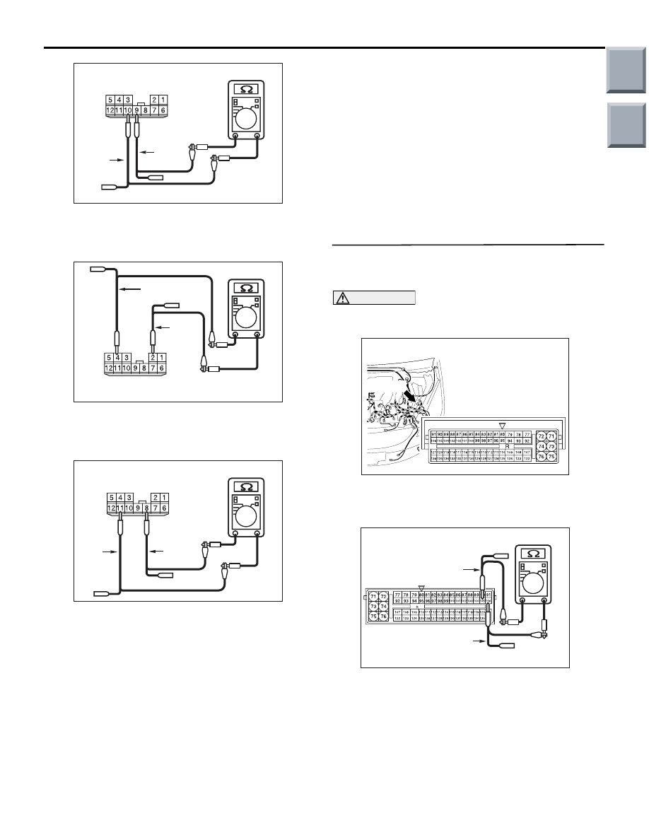
(7) Resistance between B-01 joint connector (CAN2) 

terminal Nos.8 and 11

OK: 1 k

 or more

Q: Is the check result normal?

YES <all of the measurement results are within the 
normal value> : 

Repair the wiring harness 

between joint connector (CAN2) and 
intermediate connector (B-40).

NO <The resistance between terminal Nos.1 and 5 
is less than 1 k

> : 

Go to Step 11.

NO <The resistance between terminal Nos.2 and 4 
is less than 1 k

> : 

Go to Step 9.

NO <The resistance between terminal Nos.8 and 11 
is less than 1 k

> : 

Go to Step 10.

NO <The resistance between terminal Nos.9 and 10 
is less than 120 

± 20 > : 

Go to Step 8.

STEP 8. Resistance measurement at A-08 
engine-ECU <M/T> or engine-CVT-ECU <CVT> 
connector.

CAUTION

A digital multimeter should be used. For details 
refer to 

P.54D-5

.

AC509191

Connector: A-08

Harness side

AD

A-08 (GR)

(1) Remove the engine-ECU <M/T> or 

engine-CVT-ECU <CVT>, and measure at the 
equipment side.

AC204738

AC204738FT

Equipment side: A-08

Test 
harness

Test 
harness

(2) Resistance at A-08 engine-ECU <M/T> or 

engine-CVT-ECU <CVT> connector terminal 
Nos.105 and 106

OK: 120 

± 20 

Main

Index

Group

TOC

TROUBLESHOOTING

CONTROLLER AREA NETWORK (CAN)

54D-54

Q: Is the check result normal?

YES : 

<Within 120 

± 20 Ω> Repair the wiring 

harness between joint connector (CAN2) 
and engine-ECU <M/T> or 
engine-CVT-ECU <CVT> connector.

NO : 

<Not within 120 

± 20 Ω> Check the 

engine-ECU <M/T> or engine-CVT-ECU 
<CVT> connector, and repair if necessary. If 
the engine-ECU <M/T> or engine-CVT-ECU 
<CVT> connector is in good condition, 
replace the engine-ECU <M/T> or 
engine-CVT-ECU <CVT>.

STEP 9. Resistance measurement at A-05 
ABS-ECU <vehicles without ASC> or ASC-ECU 
<vehicles with ASC> connector.

CAUTION

A digital multimeter should be used. For details 
refer to 

P.54D-5

.

AC601294

A-05 (B)

AB

Harness side

<ABS-ECU>

<ASC-ECU>

Connector: A-05

(1) Remove the ABS-ECU <vehicles without ASC> 

or ASC-ECU <vehicles with ASC>, and measure 
at the equipment side.

AC204738

AC204738FG

Equipment side: A-05

Test 
harness

Test 
harness

(2) Resistance at A-05 ASC-ECU connector terminal 

Nos.1 and 12 <vehicles without ASC>

OK: 1 k

 or more

AC204738

AC204738

AC204738

AC204738

AC204738

AC204738NM

Equipment side: A-05

Test 
harness

Test 
harness

(3) Resistance at A-05 ASC-ECU connector terminal 

Nos.38 and 39 <vehicles with ASC>

OK: 1 k

 or more

Q: Is the check result normal?

YES : 

<1 k

Ω or more> Repair the wiring harness 

between joint connector (CAN2) and 
ABS-ECU <vehicles without ASC> or 
ASC-ECU <vehicles with ASC> connector.

NO : 

<Less than 1 k

Ω> Check the ABS-ECU 

<vehicles without ASC> or ASC-ECU 
<vehicles with ASC> connector, and repair if 
necessary. If the ABS-ECU <vehicles 
without ASC> or ASC-ECU <vehicles with 
ASC> connector is in good condition, 
replace the ABS-ECU <vehicles without 
ASC> or ASC-ECU <vehicles with ASC>.

Main

Index

Group

TOC

TROUBLESHOOTING

CONTROLLER AREA NETWORK (CAN)

54D-55

STEP 10. Resistance measurement at B-37 
EPS-ECU connector.

CAUTION

A digital multimeter should be used. For details 
refer to 

P.54D-5

.

AC313820

Connector: B-37

AG

B-37 (B)

Harness side

(1) Remove the EPS-ECU, and measure at the 

equipment side.

AC204738FO

Equipment side: B-37

Test 
harness

Test 
harness

(2) Resistance at B-37 EPS-ECU connector terminal 

Nos.3 and 8

OK: 1 k

 or more

Q: Is the check result normal?

YES : 

<1 k

Ω or more> Repair the wiring harness 

between joint connector (CAN2) and 
EPS-ECU connector.

NO : 

<Less than 1 k

Ω> Check the EPS-ECU 

connector, and repair if necessary. If the 
EPS-ECU connector is in good condition, 
replace the EPS-ECU.

STEP 11. Resistance measurement at C-43 G and 
yaw rate sensor connector.

CAUTION

A digital multimeter should be used. For details 
refer to 

P.54D-5

.

AC601064

AB

C-43 (B)

Connector: C-43

Harness side

(1) Remove the G and yaw rate sensor, and 

measure at the equipment side.

AC204738

AC204738

AC204738

AC204738

AC204738

AC204738NL

Equipment side: C-45

Test 
harness

Test 
harness

(2) Resistance at C-43 G and yaw rate sensor 

connector terminal Nos.2 and 3

OK: 1 k

 or more

Q: Is the check result normal?

YES : 

<1 k

Ω or more> Repair the wiring harness 

between joint connector (CAN2) and G and 
yaw rate sensor connector.

NO : 

<Less than 1 k

Ω> Check the G and yaw rate 

sensor connector, and repair if necessary. If 
the G and yaw rate sensor connector is in 
good condition, replace the G and yaw rate 
sensor.

Main

Index

Group

TOC

TROUBLESHOOTING

CONTROLLER AREA NETWORK (CAN)

54D-56

Diagnostic Item 4: Diagnose the terminator resistors at both ends.

CAUTION

When servicing a CAN bus line, earth yourself by touching a metal object such as an unpainted water 
pipe. If you fail to do, a component connected to the CAN bus line may be broken.

ENGINE-ECU <M/T> OR
ENGINE-CVT-ECU <CVT>

COMBINATION
METER

DIAGNOSIS
CONNECTOR

Wire colour code
B : Black     LG : Light green     G : Green     L : Blue     W : White     Y : Yellow     SB : Sky blue
BR : Brown     O : Orange     GR : Grey     R : Red     P : Pink     V : Violet     PU : Purple

FUNCTION

The resistance in the communication errors condition 
cannot be measured by the CAN bus diagnostics, 
therefore, judge the terminator resistor only when 
receiving the each ECU periodically sent data nor-
mally.

TROUBLE JUDGEMENT CONDITIONS

The M.U.T.-III judges the trouble when the periodi-
cally sent data from each ECU can be received nor-
mally but the resistance value between CAN_H and 
CAN_L line is other than from 50 ohms to 70 ohms.

Main

Index

Group

TOC


Content   ..  304  305  306  307   ..