Mitsubishi Colt Ralliart. Manual - part 270
 

  Index      Mitsubishi     Mitsubishi Colt Ralliart - service repair manual


Search            


Content   ..  268  269  270  271   ..


Mitsubishi Colt Ralliart. Manual - part 270


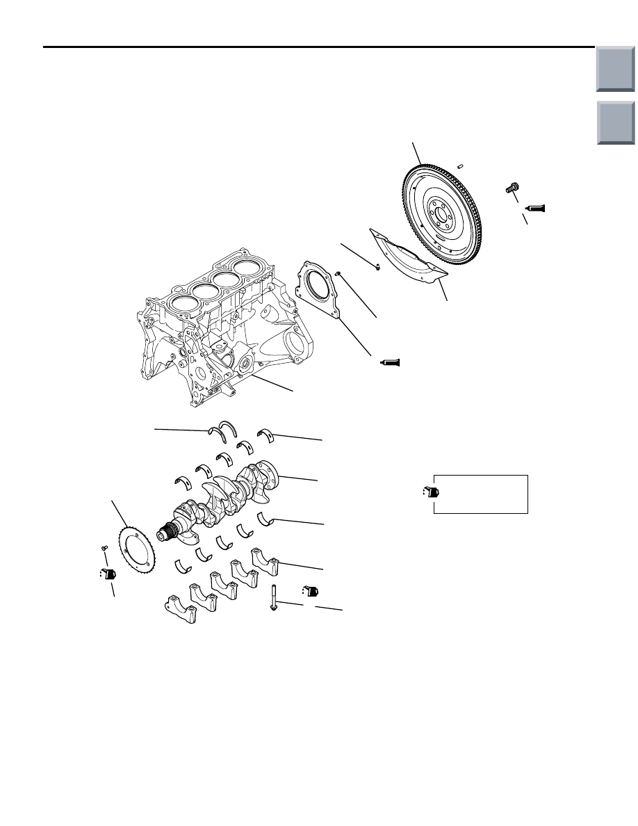
CRANKSHAFT AND CYLINDER BLOCK

ENGINE OVERHAUL <4A9>

11B-44

CRANKSHAFT AND CYLINDER BLOCK

REMOVAL AND INSTALLATION

M1113008701801

<M/T>

AK600324AB

Apply engine oil to
all moving parts
before installation.

7

10

11

8

1

6

5

4

3

2

9

35 ± 2 N·m 

→ +60˚ to 64˚

12

100 ± 5 N·m

6.7 ± 1.3 N·m

9.0 ± 1.0 N·m

7.6 ± 0.6 N·m

Removal steps 

<<

A

>> >>

G

<< 1. Fly wheel bolt

2. Fly wheel
3. Bell housing cover
4. Oil seal case

>>

F

<< 5. Crank shaft bearing cap bolt

>>

E

<< 6. Crankshaft bearing cap

>>

E

<< 7. Crankshaft bearing, lower

>>

D

<< 8. Crankshaft

9. Crankshaft bearing, upper

>>

C

<< 10.Thrust bearing

>>

B

<< 11.Crankshaft sensing ring

>>

A

<< 12.Cylinder block

Removal steps (Continued)

Main

Index

Group

TOC

CRANKSHAFT AND CYLINDER BLOCK

ENGINE OVERHAUL <4A9>

11B-45

<CVT>

AK401772 AC

Apply engine oil to
all moving parts
before installation.

7

10

11

8

1

6

5

4

3

2

9

35 ± 2 N·m 

→ +60˚ to 64˚

13

12

100 ± 5 N·m

6.7 ± 1.3 N·m

9.0 ± 1.0 N·m

7.6 ± 0.6 N·m

Removal steps 

<<

A

>> >>

G

<< 1. Drive plate bolt

2. Adapter plate
3. Drive plate
4. Bell housing cover

>>

F

<< 5. Oil seal case

>>

E

<< 6. Crankshaft bearing cap bolt

>>

E

<< 7. Crankshaft bearing cap

>>

D

<< 8. Crankshaft bearing, lower

9. Crankshaft

>>

C

<< 10.Crankshaft bearing, upper

>>

B

<< 11.Thrust bearing

>>

A

<< 12.Crankshaft sensing ring

13.Cylinder block

Removal steps (Continued)

Main

Index

Group

TOC

CRANKSHAFT AND CYLINDER BLOCK

ENGINE OVERHAUL <4A9>

11B-46

REMOVAL SERVICE POINTS
<<A>> DRIVE PLATE BOLT/FLYWHEEL 
BOLT REMOVAL

AK600410AC

MB991883

<M/T>

AK600407

MD998781

Cylinder block

Drive plate

AB

<CVT>

1. Lock the drive plate or the flywheel using the 

special tool Flywheel stopper.

2. Remove the drive plate bolt.

• Flywheel Stopper (MD998781)

• Flywheel Stopper (MB991883)

INSTALLATION SERVICE POINTS
>>A<< CRANKSHAFT SENSING RING 
INSTALLATION

AK305710

AB

1

3

2

Pin

1. Apply engine oil to the crankshaft sensing ring 

screw.

2. Tighten the crankshaft sensing ring screws to 9.0 

± 1.0 N⋅m in the steps given in the illustrated.

>>B<< THRUST BEARING INSTALLATION

1. Install the thrust bearing onto the cylinder block 

side of the No. 4 bearing. Apply engine oil to the 
thrust bearing to facilitate installation.

AK305429AB

Groove

2. The thrust bearing should be installed such that its 

groove faces the crankshaft weight.

>>C<< CRANKSHAFT BEARING UPPER 
INSTALLATION

AK305609AB

Timing chain side

No.1

No.2

No.5

No.4

No.3

1. The crankshaft bearing upper should be selected 

based on the identification mark on the bottom 
face of the cylinder block (illustrated) and the table 
shown below.

AK305606AB

Groove

Identification
color

2. Every crankshaft bearing upper is identified by the 

paint mark at the illustrated location.

Main

Index

Group

TOC

Cylinder block

Crankshaft 
bearing paint 
color

Identification 
mark

Journal 
diameter
mm

1

50.000 

− 50.005 Blue

2

50.005 

− 50.010 Black

3

50.010 

− 50.015 Red

AK305700

AC

A

B

CRANKSHAFT AND CYLINDER BLOCK

ENGINE OVERHAUL <4A9>

11B-47

3. Select and install the crankshaft bearing upper.
4. Measure the illustrated location. The error should 

be within 0.5 mm.
In case of the service part, install it aligning the 
bearing projection with the places shown in 
Figure.

>>D<< CRANKSHAFT BEARING LOWER 
INSTALLATION

AK306103

No.1

AF

No.4

No.3

No.2

Production date

No.5

1. The crankshaft bearing lower should be selected 

based on the identification mark on the crankshaft 
rear flange (illustrated) and the table shown 
below.

AK305607AB

Identification
color

2. Every crankshaft bearing lower is identified by the 

paint mark at the illustrated location.

Crankshaft

Crankshaft 
bearing paint 
color

Identification 
mark

Journal 
diameter
mm

P

46.024 

− 46.029 Blue

Y

46.019 

− 46.024 Yellow or Black

N

46.014 

− 46.019 Red

W

46.009 

− 46.014 White

B

46.004 

− 46.009 Purple

AK305695

AC

A

B

3. Select and install the crankshaft bearing lower.
4. Measure the illustrated location. The error should 

be within 0.5 mm.
In case of the service part, install it aligning the 
bearing projection with the places shown in 
Figure.

Main

Index

Group

TOC


Content   ..  268  269  270  271   ..