Mitsubishi Colt Ralliart. Manual - part 255
DRIVESHAFT ASSEMBLY
FRONT AXLE
26-20
INSTALLATION SERVICE POINTS
>>A<< DRIVESHAFT ASSEMBLY/DRIVE-
SHAFT (RH)/DRIVESHAFT (LH) INSTAL-
LATION
CAUTION
• The magnetic encoder collects any metallic
particle easily, because it is magnetized. Make
sure that the magnetic encoder should not
collect any metallic particle. Check that there
is not any trouble prior to reassembling it.
• When the driveshaft is installed, make sure
that it does not contact with the magnetic
encoder to avoid damage.
• When installing the driveshaft, be careful that
the spline part of the driveshaft do not dam-
age the oil seal.
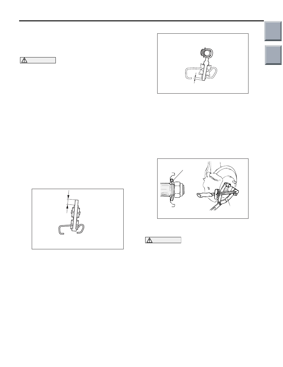
>>B<< STABILIZER
RUBBER/SELF-LOCKING
NUT/STABILIZER LINK BUSH
(B)/STABILIZER LINK
ASSEMBLY/STABILIZER LINK BUSH (A)
INSTALLATION
<4A9>
AC207017AE
A
<4A9>
Install the stabilizer rubber as shown in the figure,
and tighten the self-locking nut so that the protruding
length of the stabilizer bar mounting bolt or the pro-
truding length of the stabilizer link assembly meets
its standard value (A).
Standard value (A): 19
± 1.5 mm
<4G1>
AC403361
<4G1>
A
AF
Install the stabilizer link bush (B), stabilizer link
assembly and stabilizer link bush (A) as shown in the
figure, and tighten the stabilizer link bush (A) so that
the protruding length of the stabilizer link assembly
meets its standard value (A).
Standard value (A): 5
± 1.5 mm
>>C<< WASHER/DRIVESHAFT NUT
INSTALLATION
AC102465
Washer
MB990767
AB
1. Be sure to install the driveshaft washer in the
specified direction.
CAUTION
Before securely tightening the driveshaft nuts,
make sure there is no load on the wheel bear-
ings. Otherwise the wheel bearing will be dam-
aged.
2. Using special tool front hub & flange yoke holder
(MB990767), tighten the driveshaft nut to the
specified torque.
Tightening torque: 245
± 29 N⋅m
Main
Index
Group
TOC