Mitsubishi Colt Ralliart. Manual - part 224


  Index      Mitsubishi     Mitsubishi Colt Ralliart - service repair manual


Search            


Content   ..  222  223  224  225   ..


Mitsubishi Colt Ralliart. Manual - part 224


REAR DISC BRAKE ASSEMBLY <VR-X, RALLIART Version-R>

BASIC BRAKE SYSTEM

35A-42

REMOVAL SERVICE POINT
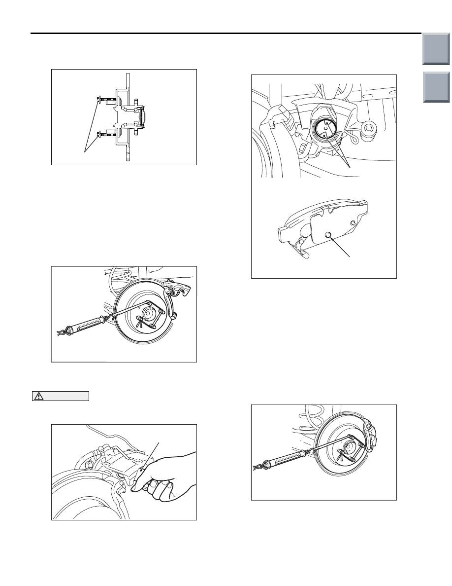
<<A>> REAR BRAKE DISC REMOVAL

AC403051

AB

Bolts (M8 x 1.25)

If the rear brake disc is seized, install M8 

× 1.25 mm 

bolts as shown, and remove the disc by tightening 
the both bolts evenly and gradually.

INSTALLATION SERVICE POINT
>>A<< REAR BRAKE CALIPER ASSEM-
BLY INSTALLATION

Measure the brake drag force in the following proce-
dure.

AC402633

1. Using a spring balance, measure the hub sliding 

torque in the forward direction.

CAUTION

Keep grease or other fouling off the pad and 
brake disc friction surface. 

AC402607AB

MB990652

2. Clean the piston, and press the piston into the 

cylinder using the special tool, disc brake piston 
driver (MB990652).

3. Install the caliper support to the backing plate 

assembly, and assemble the pad clip and pad to 
the caliper support.

AC403232AB

Stopper groove

Protrusion

4. Set as shown so that the protrusion on the pad 

assembly rear face is engaged in the piston 
stopper groove.

5. Lower the caliper assembly while taking care not 

to catch the piston boot, and tighten the bolt to the 
specified torque.

Tightening torque: 27 

± 4 Nm

6. Start the engine, and depress the brake pedal 

forcibly two or three times. Then stop the engine.

7. Rotate the brake disc 10 turns in the forward 

direction.

AC402632

8. Using a spring balance, measure the hub sliding 

torque in the forward direction.

9. Obtain the disc brake drag force (difference 

between measured values of item 1 and item 7).

Standard value: 46 N or less.

Main

Index

Group

TOC

REAR DISC BRAKE ASSEMBLY <VR-X, RALLIART Version-R>

BASIC BRAKE SYSTEM

35A-43

10.If the brake drag force exceeds the standard 

value, disassemble the piston to check for 
fouling/rust on the piston sliding section and 
piston/seal deterioration, and confirm whether the 
slide pin slides properly.

REMOVAL AND INSTALLATION 
<RALLIART VERSION-R>

M1351007000648

Pre-removal Operation
Brake fluid draining

Post-installation Operation
Brake fluid refilling and air bleeding (Refer to 

P.35A-10

).

AC312919AC

60 ± 5 N·m

15 ± 2 N·m

1

2

3

Removal steps 

Connection between parking brake 
rear cable and rear brake caliper 
assembly

1.

Connection between brake hose 
and rear brake caliper assembly

>>

A

<<

2.

Rear brake caliper assembly

3.

Rear brake disc

Removal steps (Continued)

Main

Index

Group

TOC

REAR DISC BRAKE ASSEMBLY <VR-X, RALLIART Version-R>

BASIC BRAKE SYSTEM

35A-44

INSTALLATION SERVICE POINT
>>A<< REAR BRAKE CALIPER ASSEM-
BLY INSTALLATION

Measure the brake drag force in the following proce-
dure.

AC402633

1. Using a spring balance, measure the hub sliding 

torque in the forward direction.

CAUTION

Keep grease or other fouling off the pad and 
brake disc friction surface. 

AC402607AD

MB996049

2. Clean the piston, and press the piston into the 

cylinder using the special tool, disc brake piston 
driver (MB996049).

3. Install the caliper support to the backing plate 

assembly, and assemble the pad clip and pad to 
the caliper support.

4. Lower the caliper assembly while taking care not 

to catch the piston boot, and tighten the bolt to the 
specified torque.

Tightening torque: 28 

± 2 Nm

5. Start the engine, and depress the brake pedal 

forcibly two or three times. Then stop the engine.

6. Rotate the brake disc 10 turns in the forward 

direction.

AC402632

7. Using a spring balance, measure the hub sliding 

torque in the forward direction.

8. Obtain the disc brake drag force (difference 

between measured values of item 1 and item 7).

Standard value: 46 N or less

9. If the brake drag force exceeds the standard 

value, disassemble the piston to check for 
fouling/rust on the piston sliding section and 
piston/seal deterioration, and confirm whether the 
slide pin slides properly.

Main

Index

Group

TOC

REAR DISC BRAKE ASSEMBLY <VR-X, RALLIART Version-R>

BASIC BRAKE SYSTEM

35A-45

DISASSEMBLY AND REASSEMBLY 
<VR-X>

M1351007200619

AC403012

AB

Clip set

7

7

4

4

Pad set

5

Shim kit

6

6

Repair kit 
grease

Seal & boot kit

17

3

16

15

24

10

13

Brake caliper kit

21

14

27

19

11

20

17

12

18

16

13

15

24

22

23

25

8

10

9

26

1

2

3

24

25

11

17

13

21

19

4

18

16

6

15

7

20

7

22

8

10

9

26

2

3

14

23

6

4

12

27

7.9 ± 0.9 N·m

27 ± 4 N·m

27 ± 4 N·m

1

Disassembly steps 

1.

Lock pin

2.

Sleeve

3.

Sleeve boot

4.

Pad assembly

5.

Pad and wear indicator assembly

6.

Shim

7.

Clip

8.

Return spring

9.

Parking brake lever

10. Lever boot
11. Guide pin
12. Guide pin sleeve
13. Guide pin boot

14. Support mounting
15. Boot ring

<<

A

>>

16. Piston boot

<<

B

>>

17. Piston seal

<<

A

>>

>>

B

<<

18. Piston

<<

C

>>

>>

A

<<

19. Snap ring
20. Snap case
21. Return spring
22. Stopper
23. Adjuster spindle
24. O-ring
25. Connecting link

Disassembly steps (Continued)

Main

Index

Group

TOC


Content   ..  222  223  224  225   ..