Mitsubishi Colt Ralliart. Manual - part 199
 

  Index      Mitsubishi     Mitsubishi Colt Ralliart - service repair manual


Search            


Content   ..  197  198  199  200   ..


Mitsubishi Colt Ralliart. Manual - part 199


ON-VEHICLE SERVICE

CVT

23A-139

TORQUE CONVERTER STALL TEST

M1231205400117

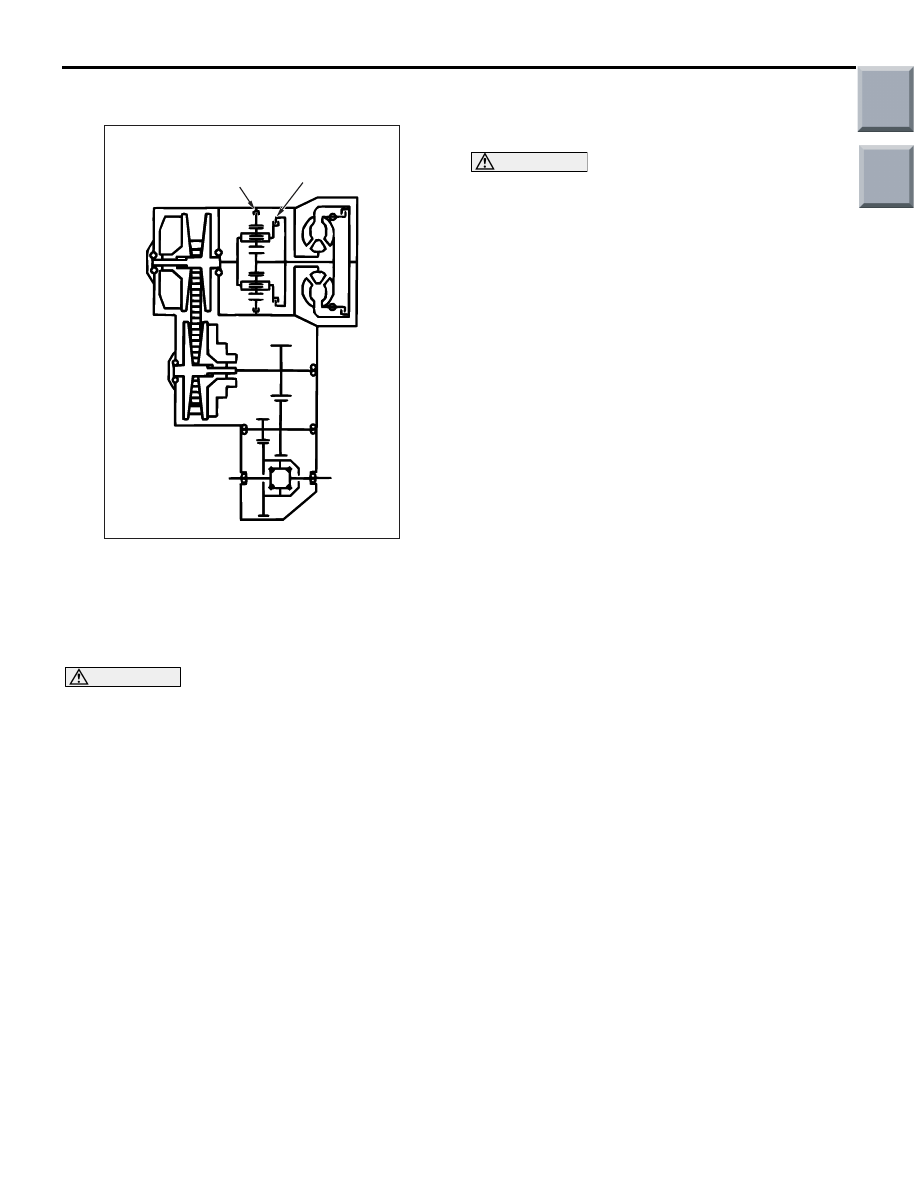
AC208197AB

Reverse brake

Forward clutch

The purpose of this test is to measure the maximum 
engine speed when the torque converter stalls in D 
or R ranges in order to check the torque converter 
(Stator and one-way clutch operation) and the hold-
ing performance of the clutches and brakes which 
are built into the transmission.

WARNING

For safety, the front and rear of the vehicle 
should be kept clear of other people while 
this test is being carried out.

1. Check the CVT fluid level, the CVT fluid 

temperature and the engine coolant temperature.

• CVT fluid level: HOT position on oil level gauge

• CVT fluid temperature: 70 − 80°C

• Engine coolant temperature: 80 − 100°C

NOTE: The CVT fluid temperature is measured 
with M.U.T.-III.

2. Raise the vehicle.

3. Pull the parking brake lever to apply the parking 

brake and depress the brake pedal fully.

4. Start the engine.

CAUTION

• Do not keep the throttle fully open for any 

longer than 5 seconds.

• If you repeat the stall test when the CVT fluid 

temperature is greater than 80

°C, move the 

selector lever to the "N" position and let the 
engine run at approximately 1,000 r/min for at 
least one minute. Wait until the CVT fluid tem-
perature returns to 80

°C or less.

5. Move the selector lever to the D position, fully 

depress the accelerator pedal and quickly take a 
reading of the maximum engine speed at this 
time.

Standard stalling engine speed: 2,200 

 2,700 

r/min

6. Move the selector lever to the R position and 

repeat the test described above.

Standard stalling engine speed: 1,800 

 2,300 

r/min

TORQUE CONVERTER STALL TEST 
JUDGMENT RESULTS

1. Stall speed is too high in both D and R ranges

• Malfunction of the torque converter (Slippage 

on the splines of the torque converter and the 
input shaft)

• Malfunction of the valve body

• Damaged harness and connector

• Malfunction of the engine-CVT-ECU

2. Stall speed is too high in D range only

• Forward clutch slippage

3. Stall speed is too high in R range only

• Reverse brake slippage

4. Stall speed is too low in both D and R ranges

• Malfunction of the torque converter (Slippage 

of the one-way clutch)

• Low line pressure

• Poor engine output

Main

Index

Group

TOC

ON-VEHICLE SERVICE

CVT

23A-140

HYDRAULIC PRESSURE TESTS

M1231205500062

CAUTION

The CVT fluid temperature should be between 70 
 80°C during the test.
1. Check the CVT fluid level, temperature and 

engine coolant temperature.

• CVT fluid level: HOT mark on the dipstick

• CVT fluid temperature: 70 − 80°C

• Engine coolant temperature: 80 − 100°C

2. Stop the engine and raise the vehicle.

AC201916AB

MD998330

MD998331

MD998332

Valve body cover

AC208198AB

MD998330

MD998331

MD998332

Valve body cover

3. Connect the following special tools to each 

pressure discharge port.

• Oil pressure gauge <3.0 MPa> (MD998330)

• Oil pressure gauge joint (MD998331)

• Hose adapter (MD998332)

NOTE: 

.

DA: Torque converter apply pressure port
DR: Torque converter release pressure port
2WD: Forward clutch pressure port
REV: Reverse brake pressure port
RED: Reducing pressure port
NOTE: For details on the primary pressure and 
line pressure, refer to the M.U.T.-III service data. 
(Refer to 

P.23A-123

).

4. Restart the engine.
5. Check that there are no leaks around the special 

tool port adapters.

6. Pull the parking brake lever, and step on the brake 

pedal completely. (Continue stepping on the pedal 
during measurement).

WARNING

For safety, the front and rear of the vehicle 
should be kept clear of other people while 
this test is being carried out.

CAUTION

Do not make measurement with the selector 
lever at the R, D, Ds or L range for more than 30 
seconds to prevent excessive oil pressure. If you 
repeat this operation, let the engine run at idle for 
at least one minute by moving the selector lever 
at the N or P range.
7. Measure the hydraulic pressure at each port 

under the conditions given in the standard 
hydraulic pressure table, and check that the 
measured values are within the standard value 
ranges.

8. If the pressure is not within the standard value, 

stop the engine and refer to the hydraulic 
pressure test diagnosis table.

9. Remove the O-ring from the port plug and replace 

it.

10.Remove the special tool, and install the plugs to 

the hydraulic pressure ports.

11.Start the engine and check that there are no leaks 

around the plugs.

Main

Index

Group

TOC

ON-VEHICLE SERVICE

CVT

23A-141

STANDARD HYDRAULIC PRESSURE TABLE

Measurement 
condition

Standard hydraulic pressure MPa

Selector 
lever 
position

Engine 
speed 
(r/min)

Forward 
clutch 
pressure 
[2WD 
pressure]

Reverse 
brake 
pressure 
[REV 
pressure]

Reducing 
pressure 
[RED 
pressure]

Primary 
pressure

Line 
pressure

Torque 
converter 
pressure 
[DR 
pressure]

P

1,500

0

0

0.4 

− 0.6

0.2 

− 1.1

0.6 

− 3.0

0.4 

− 0.6

R

1,500

0

1.0 

− 1.4

0.4 

− 0.6

0.4 

− 1.1

1.0 

− 3.0

0.4 

− 0.6

N

1,500

0

0

0.4 

− 0.6

0.2 

− 1.1

0.6 

− 3.0

0.4 

− 0.6

D

1,500

0.9 

− 1.1

0

0.4 

− 0.6

0.4 

− 1.1

1.0 

− 3.0

0.4 

− 0.6

Ds

1,500

0.9 

− 1.1

0

0.4 

− 0.6

0.4 

− 1.1

1.0 

− 3.0

0.4 

− 0.6

L

1,500

0.9 

− 1.1

0

0.4 

− 0.6

0.4 

− 1.1

1.0 

− 3.0

0.4 

− 0.6

HYDRAULIC PRESSURE TEST DIAGNOSIS TABLE

Trouble symptom

Probable cause

All hydraulic pressures are high

Improper measurement

All hydraulic pressures are low

Malfunction of the oil pump
Clogged internal oil filter
Clogged oil cooler
Malfunction of the regulator valve
Incorrect valve body installation

Only forward clutch hydraulic pressure is 
abnormal

Malfunction of the manual valve
Malfunction of the clutch pressure control valve
Malfunction of the clutch pressure reducing valve
Malfunction of the clutch pressure control solenoid valve
Clogged orifice
Incorrect valve body installation
Malfunction of the oil seal A, B, C

Only reverse brake hydraulic pressure is 
abnormal

Malfunction of the manual valve
Malfunction of the clutch pressure control valve
Malfunction of the clutch pressure reducing valve
Malfunction of the clutch pressure control solenoid valve
Clogged orifice
Incorrect valve body installation

Only reducing pressure is abnormal

Malfunction of the reducing valve
Clogged orifice
Incorrect valve body installation

Main

Index

Group

TOC

ON-VEHICLE SERVICE

CVT

23A-142

OIL SEAL LAYOUT

AC107065AB

A

A

B

C

D

E

F

Only line pressure is abnormal

Clogged orifice
Malfunction of the regulator valve
Incorrect valve body installation

Only torque converter output pressure is 
abnormal

Malfunction of the damper clutch control valve
Malfunction of the damper clutch control solenoid valve
Malfunction of the torque converter pressure control valve
Clogged orifice
Incorrect valve body installation
Malfunction of the torque converter
Malfunction of the oil seal D, E, F

Pressure applied to element which should 
not receive pressure

Incorrect transmission control cable adjustment
Malfunction of the manual valve
Incorrect valve body installation

Trouble symptom

Probable cause

Main

Index

Group

TOC


Content   ..  197  198  199  200   ..