Mitsubishi Colt Ralliart. Manual - part 183
 

  Index      Mitsubishi     Mitsubishi Colt Ralliart - service repair manual


Search            


Content   ..  181  182  183  184   ..


Mitsubishi Colt Ralliart. Manual - part 183


TROUBLESHOOTING <CVT>

CVT

23A-75

STEP 15. Measure the voltage at 
engine-CVT-ECU connector A-114.
(1) Connect primary pressure sensor connector 

A-118.

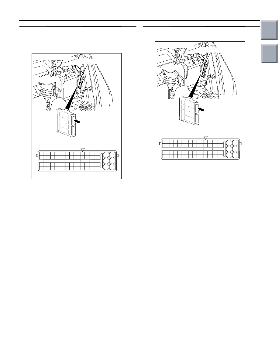
AC403088AF

A-114

Connector: A-114

6

4

2

5

3

1

9

7

8

10

11

12

13

14

15

16

17

18

19

20

21

22

23

24

25

26

27

28

29

30

31

32

33

34

35

36

37

38

39

40

41

42

43

44

45

46

47

48

49

50

51

52

53

54

55

56

57

58

59

60

61

62

63

64

65

66

L

A-114 Check connector (special tool)

Engine-CVT-ECU

Battery

(GR)

(2) Disconnect the engine-CVT-ECU connector, and 

connect the special tool Power plant ECU check 
harness (MB991987).

(3) Let the engine run at idle.
(4) Shift the selector lever to the P range.
(5) Close the accelerator pedal fully.
(6) Use the special tool Check connector to measure 

the voltage between engine-CVT-ECU connector 
A-114 terminal No.41 and earth.

OK: 0.5 

 0.9 V

Q: Is the check result normal?

YES : . 

Go to Step 18.

NO : . 

Go to Step 16.

STEP 16. Connector check: A-114 
engine-CVT-ECU connector.

AC403088AG

A-114

Connector: A-114

6

4

2

5

3

1

9

7

8

10

11

12

13

14

15

16

17

18

19

20

21

22

23

24

25

26

27

28

29

30

31

32

33

34

35

36

37

38

39

40

41

42

43

44

45

46

47

48

49

50

51

52

53

54

55

56

57

58

59

60

61

62

63

64

65

66

L

A-114 Harness side connector

Engine-CVT-ECU

Battery

(GR)

Check for the contact with terminals.

Q: Is the check result normal?

YES : 

Go to Step 17.

NO : 

Repair the defective connector.

Main

Index

Group

TOC

TROUBLESHOOTING <CVT>

CVT

23A-76

STEP 17. Check the harness between primary 
pressure sensor connector A-118 terminal No.2 
and engine-CVT-ECU connector A-114 terminal 
No.41.

AC206690

AF

Connector: A-118

A-118 (B)

Harness side

1

2

3

AC403088AG

A-114

Connector: A-114

6

4

2

5

3

1

9

7

8

10

11

12

13

14

15

16

17

18

19

20

21

22

23

24

25

26

27

28

29

30

31

32

33

34

35

36

37

38

39

40

41

42

43

44

45

46

47

48

49

50

51

52

53

54

55

56

57

58

59

60

61

62

63

64

65

66

L

A-114 Harness side connector

Engine-CVT-ECU

Battery

(GR)

Check the output line for short-circuited or open cir-
cuit.

Q: Is the check result normal?

YES : 

Replace the primary pressure sensor. 

(Refer to 

P.23A-155

).

NO : 

Repair the wiring harness.

STEP 18. Connector check: A-114 
engine-CVT-ECU connector.

AC403088AG

A-114

Connector: A-114

6

4

2

5

3

1

9

7

8

10

11

12

13

14

15

16

17

18

19

20

21

22

23

24

25

26

27

28

29

30

31

32

33

34

35

36

37

38

39

40

41

42

43

44

45

46

47

48

49

50

51

52

53

54

55

56

57

58

59

60

61

62

63

64

65

66

L

A-114 Harness side connector

Engine-CVT-ECU

Battery

(GR)

Check for the contact with terminals.

Q: Is the check result normal?

YES : 

Go to Step 6.

NO : 

Repair the defective connector.

Main

Index

Group

TOC

TROUBLESHOOTING <CVT>

CVT

23A-77

Code No.31 Line Pressure Control Solenoid Valve System

CVT CONTROL
SOLENOID
VALVE
ASSEMBLY

CLUTCH
PRESSURE
CONTROL
SOLENOID
VALVE

SHIFT
CONTROL
SOLENOID
VALVE

DAMPER
CLUTCH
CONTROL
SOLENOID
VALVE

LINE
PRESSURE
CONTROL
SOLENOID
VALVE

ENGINE-
CVT-ECU

Wire colour code
B : Black     LG : Light green     G : Green     L : Blue     W : White     Y : Yellow     SB : Sky blue
BR : Brown     O : Orange     GR : Gray     R : Red     P : Pink     V : Violet

Solenoid Valve System Circuit

AC405424

OPERATION

The line pressure control solenoid valve controls the 
fluid pressure applied on the secondary pulley by 
using the signal from the engine-CVT-ECU.

DIAGNOSIS CODE SET CONDITIONS

If the line pressure control solenoid valve driving volt-
age is 3 V or less, code No.31 will be set.

PROBABLE CAUSES

• Malfunction of line pressure control solenoid 

valve

• Damaged harness wires and connectors

• Malfunction of the engine-CVT-ECU

DIAGNOSIS PROCEDURE

STEP 1. M.U.T.-III diagnosis code

Q: Are diagnosis codes 33, 37 set?

YES : 

Go to Step 9.

NO : 

Go to Step 2.

Main

Index

Group

TOC

TROUBLESHOOTING <CVT>

CVT

23A-78

STEP 2. M.U.T.-III actuator test
Item 01: Line pressure control solenoid valve

OK: Operating sound can be heard.

Q: Is the check result normal?

YES : 

Intermittent malfunction (Refer to GROUP 

00 

− How to Cope with Intermittent 

Malfunction 

P.00-13

).

NO : 

Go to Step 3.

STEP 3. Connector check: A-117 CVT control 
solenoid valve assembly connector.

AC314190

AC

Inhibitor switch

Transmission 
control cable

A-117 (GR)

Connector: A-117

Harness side

Check for the contact with terminals.

Q: Is the check result normal?

YES : 

Go to Step 4.

NO : 

Repair the defective connector.

STEP 4. Measure the resistance at CVT control 
solenoid valve assembly connector A-117.

AC314190

AC

Inhibitor switch

Transmission 
control cable

A-117 (GR)

Connector: A-117

Harness side

Disconnect the connector, and measure the resist-
ance between terminal 6 and 10 at the solenoid 
valve side.

OK: 2.9 

 3.5  (CVT fluid temperature at 

20

°C)

Q: Is the check result normal?

YES : 

Go to Step 5.

NO : 

Replace the line pressure control solenoid 
valve. (Refer to 

P.23A-155

).

STEP 5. Measure the voltage at engine-CVT-ECU 
connector A-114.
(1) Connect CVT control solenoid valve assembly 

connector A-117.

AC403088AF

A-114

Connector: A-114

6

4

2

5

3

1

9

7

8

10

11

12

13

14

15

16

17

18

19

20

21

22

23

24

25

26

27

28

29

30

31

32

33

34

35

36

37

38

39

40

41

42

43

44

45

46

47

48

49

50

51

52

53

54

55

56

57

58

59

60

61

62

63

64

65

66

L

A-114 Check connector (special tool)

Engine-CVT-ECU

Battery

(GR)

(2) Disconnect the engine-CVT-ECU connector, and 

connect the special tool Power plant ECU check 
harness (MB991987).

(3) Let the engine run at idle.
(4) Shift the selector lever to the P range.
(5) Use the special tool Check connector to measure 

the voltage between engine-CVT-ECU connector 
A-114 terminal No.4 and earth.

OK: 10 

 11 V

Q: Is the check result normal?

YES : 

Go to Step 8.

NO : 

Go to Step 6.

Main

Index

Group

TOC


Content   ..  181  182  183  184   ..